15
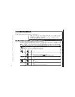
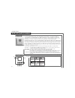
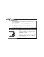
During normal operation the power LED will be ON when the master control is energised. The red output Channel LED’s
(1 to 8 on the master, and 9 to 14 on the add-on module) will indicate if the channel output relay is ON/OFF.
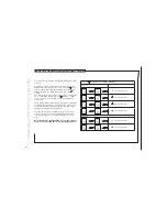
An error / fault message is shown by fl ashing the power LED or one of the red output Channel LED’s. From the number of fl ashes
on any one LED, the problem can be diagnosed, and identifi ed from the following:
The error number will be indicated by the number of fl ashes, with a pause of less than a 1/2 second between the fl ashes. The indication will be followed by a
pause of 2 seconds, following which the sequence will be repeated. The failure code can also be seen in the service menu on WLM2-FS MASTERS (submenu 2).
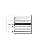
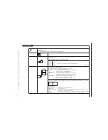
Flashing Power LED (Red and green)
Communication to the network has errors. On the network master it tells that one or more masters are not communicating. On a network slave it tells that
communication to the network master is missing.
Flashing Power LED (Red)
E1, 1 fl ash
One or more room sensors, room controllers, WLH, WLAC that are set to channel 0 or channel 15 are no longer sending data to the master
control. The fault is corrected by replacing the room sensor. The master will need to be HARD RESET (see next page “HARD RESET”)
(NOTE: If the room sensor is of the WIRELESS type, the error/fault message could be an indication that the power has failed,
and that the internal battery of the room sensor needs to be replaced)
E2, 2 fl ashes
One or more room sensors have been set to a channel number which does not exist in the system. For example, the message will occur
if the units are set to channels 9-14 and the required add on (AO) module are not found in the system. The error is corrected by setting
the channel number of the room sensor to a channel that does exist within the installed master/add on module system.
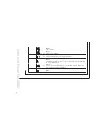
E3, 3 fl ashes
Application sensor defect. The fault is corrected by changing the temperature sensor. If the sensor has been removed deliberately to
change the operation of the system, follow the HARD RESET instruction below.
E4, 4 fl ashes
The outdoor compensation module (WLOC) is defective. The fault is corrected by changing the outdoor compensation module.
If the module has been removed deliberately to change the operation of the system, follow the HARD RESET instruction below.
E5, 5 fl ashes
The external Supply limit sensor (type ETF-1899A) is defective. The fault is corrected by changing the temperature sensor. If the
sensor has been removed deliberately to change the operation of the system, follow the HARD RESET instruction below.
E6, 6 fl ashes
Internal overheating. The master has its own internal safety temperature protection system. The problem is corrected by improving the
ventilation around the master module.
E7, 7 fl ashes
Defective internal overheat sensor. The Master will control as normal, however the protection against internal over heating is no
longer active. The fault can only be corrected by replacing the master module.
E8, 8 fl ashes
The communication to the AO module has been lost. The fault is corrected by re-establishing the connection to the AO module or by
changing the AO module if it is defective - or if it has been deliberately removed, with a HARD RESET.
E9, 9 fl ashes
Indicates total number of input units exceeded. Please refer to factory or your local service engineer.
E10, 10 fl ashes No connection to wireless receiver, type WLRC2-19.
E11, 11 fl ashes Step 2 on 2-step controller (WLCT2-X9/2) is used by another room sensor/controller.
Only one error/fault condition can be shown at a time. If more than one error occurs, they will be prioritised in the shown sequence (E1, 2, 3…).
Error Indication

