p. 16
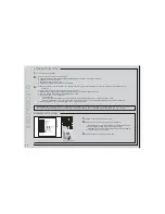
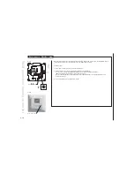
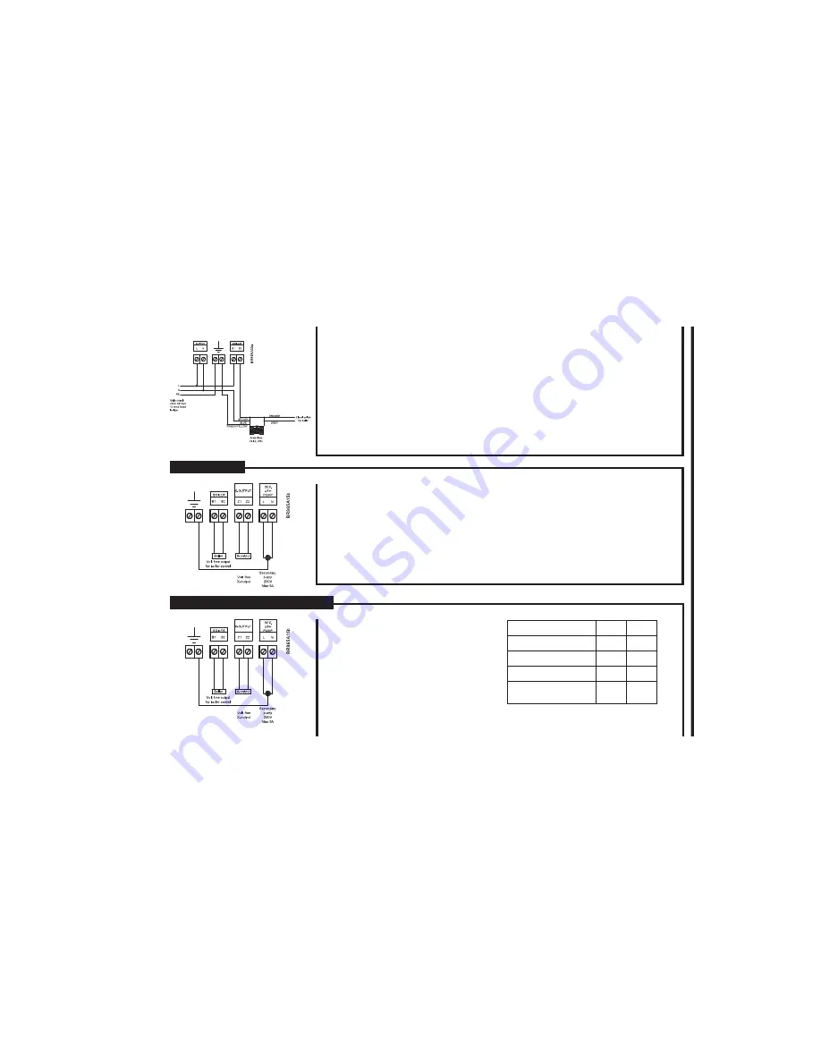
C) To control a motorised valve:
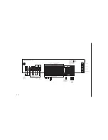
Many motorised valves have wires coloured BROWN and BLUE for power connections. In this
case BROWN goes to the terminal B2 under the heading BOILER and BLUE goes to the N
terminal of the master. Then a link from L (230V) to the terminals marked “Boiler B1”. The boiler
relay will be energised after a delay of 10 sec after the start of the main pump.
Basic versions without display. Type WLM2-1BA and WLM2-3BA The boiler relay will stop if
there is no heat demand measured by the Room sensors.
Versions with display. Type WLM2-1FS and WLM2-3FS.
These units have supply water temperature control, and the boiler relay will be ON once the
control valve has reached 20% open, and will remain on as long as a heat demand exists.
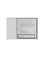
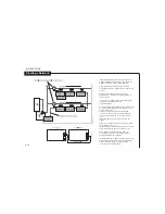
The master has an output for the underfloor circulating pump (secondary pump). The output will be
energised after a 180 sec. delay when any connected room sensor calls for heat. The delay is to
allow time for the thermal actuator to start opening.
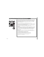
The 230v AC pump can be connected directly to terminals L and N under the heading “Sec. UFH
Pump”. Connect the pump E (Earth) terminal to E (earth) on the master. The maximum pump load
must not exceed 4 amps , 230v at start up. There is an overrun period of 1 minute after the demand
for heat from the room sensor disappears.
Delay times:
Secondary UHF pump
180 sec.
X-output (configured as main pump) 190 sec.
Pump Output
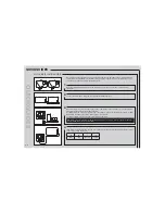
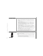
Free relay function (X-OUTPUT):
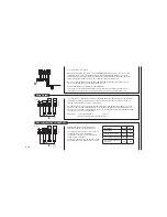
All WLM master have a relay which can be
utilized for a number of different purposes.
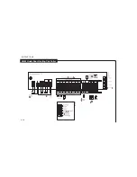
The relay is a volt free output and is positioned
on the PCB as shown on the drawing.
The function of the relay is determined by the
setting of the DIP-switches.
The functions that the relay can perform, and the
appropriate DIP-switch settings, are as follows:
To control:
Dip-5
Dip-6
Boiler pump
Off
Off
High limit zone valve*
On
Off
Cooling device/module**
Off
On
Cooling device/module
alternative
On
On
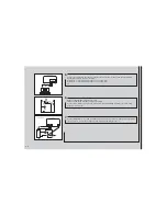
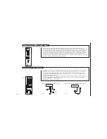
Fig. 5
Fig. 8a


