ASSEMBLY AND
INSTALLATION PROCESS
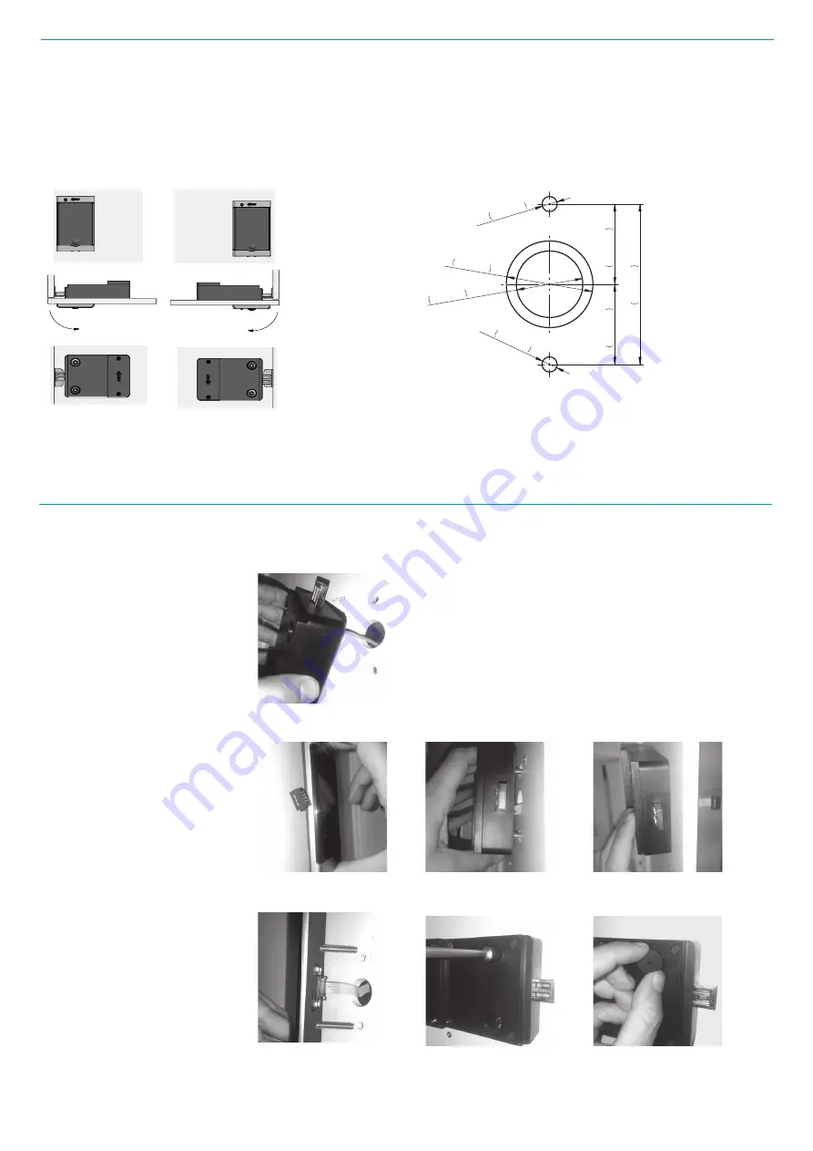
The steps to follow to assemble the
lock on the unit must be followed in
this order:
1.- Mark the holes according to
the template and drill. The surface
where the lock is installed should be
smooth and clean.
2.- Remove the plastic from the
adhesive on the rear part and pass
the cable through the hole in the
middle not resting the mechanics on
the door.
3.- Position the front part and not
connecting the mechanical part’s
cable. When the screws are guiding
the rear part tighten it strongly
against the door until it is fixed.
4.- Remove the front and connect
the cable into the connector until
you hear three beeps accompanied
by three amber flashes of the LED.
Mount the front while holding the
rear section so that it does not fall
off.
5.- Screw using two M5 nuts and an
8 box spanner. A tightening torque
of 250 Ncm should not be exceeded
when screwing each nut.
6.-Put the two trim caps on. Insert
a sharp object in the middle hole to
disassemble the caps.
(*) NOTE: During installation, make
sure that the lock does not hit the
locker body with the door open.
2
3A
3B
3C
4
5
6
The dimensions and location
of the fixing holes are shown in
the following figures:
LOCK DIRECTION
Lock assembly depending
on if it is right handed or left
handed is as follows.
Derecha
Right
Rechts
Droite
Izquierda
Left
Links
Gauche
Ø
Ø
Ø
55,5mm 2,185"
27,75mm 1,093"
5,2mm
0,205"
23mm
0,906"
30mm
1,181"
Recommend
Minimun
Ø
5,2mm
0,205"
27,75mm 1,093"
1


