PHYSICAL INSTALLATION
Oki BV1250 Installation Guide
Page 142 of 334
Revision 1.0
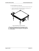
To install the line interface board:
1.
Attach ESD protection device(s) to protect against static discharge.
2.
Orient board with the component side down and the socket connectors facing
the front of the base unit.
3.
Insert board onto chassis support (above main board).
Figure 4-2: Line interface board installation
For E&M line interface boards only, configure DIP switches if
necessary before installing the board in the unit chassis. See
Section 4.3.2 for details.
4.
Slide board forward in chassis so that board connectors pass through the socket
connector cutouts at the front of the chassis.
Do not use undue force.
5.
Make final adjustments so that the screw holes are properly aligned with holes
on chassis board mount.
6.
Secure board with the six supplied screws.
Line Interface board
Summary of Contents for BV1250
Page 1: ...BV1250 Internet Voice Gateway INSTALLATION GUIDE Oki Electric Industry Co Ltd...
Page 2: ......
Page 12: ...INTRODUCTION Oki BV1250 Installation Guide Page 2 of 334 Revision 1...
Page 18: ...OVERVIEW Oki BV1250 Installation Guide Page 8 of 334 Revision 1 0...
Page 20: ...PLANNING Oki BV1250 Installation Guide Page 10 of 334 Revision 1 0...
Page 142: ...FXO WORKSHEETS Oki BV1250 Installation Guide Page 132 of 334 Revision 1 0...
Page 144: ...PHYSICAL INSTALLATION Oki BV1250 Installation Guide Page 134 of 334 Revision 1 0...
Page 184: ...LOGICAL INSTALLATION Oki BV1250 Installation Guide Page 174 of 334 Revision 1 0...
Page 270: ...APPENDICES Oki BV1250 Installation Guide Page 260 of 334 Revision 1 0...
Page 329: ...Oki BV1250 Installation Guide APPENDICES Revision 1 0 Page 319 of 334...
Page 343: ...Oki BV1250 Installation Guide APPENDICES Revision 1 0 Page 333 of 334...
Page 344: ...APPENDICES Oki BV1250 Installation Guide Page 334 of 334 Revision 1 0...


