Oki BV1250 Installation Guide
PHYSICAL INSTALLATION
Revision 1.0
Page 167 of 334
Wiring for E&M-OD Connector
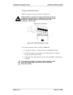
E&M-OD connector wiring is shown below in Figure 4-29.
During installation, connectors are aligned upside-down so that the
connections are made 6-5-4-3-2-1 rather than 1-2-3-4-5-6. Be certain
to check the connector labels for each connection to avoid
reversing the specified order.
Figure 4-29: E&M-OD connector wiring
To connect the interface cables to the BV1250-E&M-OD.
1.
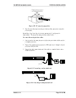
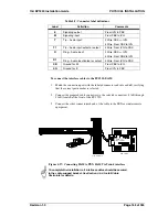
Verify the port numbers to be interconnected with the PBX trunk lines.
2.
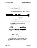
Connect the prepared cable connectors to the OD connectors (1 through 4)
located at the front of the BV1250.
3.
Connect the other connectorized end of the cable to the PBX or similar remote
equipment.
To complete the installation, all interface cables should be secured
to the cable support bracket. See Section 4.5.4, Install Cable
Restraints for details.
Summary of Contents for BV1250
Page 1: ...BV1250 Internet Voice Gateway INSTALLATION GUIDE Oki Electric Industry Co Ltd...
Page 2: ......
Page 12: ...INTRODUCTION Oki BV1250 Installation Guide Page 2 of 334 Revision 1...
Page 18: ...OVERVIEW Oki BV1250 Installation Guide Page 8 of 334 Revision 1 0...
Page 20: ...PLANNING Oki BV1250 Installation Guide Page 10 of 334 Revision 1 0...
Page 142: ...FXO WORKSHEETS Oki BV1250 Installation Guide Page 132 of 334 Revision 1 0...
Page 144: ...PHYSICAL INSTALLATION Oki BV1250 Installation Guide Page 134 of 334 Revision 1 0...
Page 184: ...LOGICAL INSTALLATION Oki BV1250 Installation Guide Page 174 of 334 Revision 1 0...
Page 270: ...APPENDICES Oki BV1250 Installation Guide Page 260 of 334 Revision 1 0...
Page 329: ...Oki BV1250 Installation Guide APPENDICES Revision 1 0 Page 319 of 334...
Page 343: ...Oki BV1250 Installation Guide APPENDICES Revision 1 0 Page 333 of 334...
Page 344: ...APPENDICES Oki BV1250 Installation Guide Page 334 of 334 Revision 1 0...


