PHYSICAL INSTALLATION
Oki BV1250 Installation Guide
Page 170 of 334
Revision 1.0
4.7
Connect the Network Cable
A standard 10BaseT cable with an RJ45 connector is used to interconnect
the BV1250 unit with a network device.
To install the Network connector cable:
1.
Insert the RJ45 connector into the BV1250 UPLINK port located on the unit’s
front panel.
Figure 4-33: Uplink connector location
2.
Connect the other end of the 10BaseT cable to the remote LAN equipment (e.g.
router, Ethernet switch, or hub.)
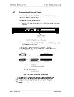
When connecting the BV1250 directly to a router use a 10BaseT
Cross/Rollover cable. Use a 10baseT straight cable to connect the BV1250
to a hub or Ethernet switch.
Figure 4-34
:
Router and Ethernet Switch cabling
As cable lengths increase voice quality may become degraded. Line
repeaters can be used when long cable lengths are required. Voice
quality may also deteriorate when hubs are connected in tandem
and tandem arrangements should never exceed more than three
stages.
Summary of Contents for BV1250
Page 1: ...BV1250 Internet Voice Gateway INSTALLATION GUIDE Oki Electric Industry Co Ltd...
Page 2: ......
Page 12: ...INTRODUCTION Oki BV1250 Installation Guide Page 2 of 334 Revision 1...
Page 18: ...OVERVIEW Oki BV1250 Installation Guide Page 8 of 334 Revision 1 0...
Page 20: ...PLANNING Oki BV1250 Installation Guide Page 10 of 334 Revision 1 0...
Page 142: ...FXO WORKSHEETS Oki BV1250 Installation Guide Page 132 of 334 Revision 1 0...
Page 144: ...PHYSICAL INSTALLATION Oki BV1250 Installation Guide Page 134 of 334 Revision 1 0...
Page 184: ...LOGICAL INSTALLATION Oki BV1250 Installation Guide Page 174 of 334 Revision 1 0...
Page 270: ...APPENDICES Oki BV1250 Installation Guide Page 260 of 334 Revision 1 0...
Page 329: ...Oki BV1250 Installation Guide APPENDICES Revision 1 0 Page 319 of 334...
Page 343: ...Oki BV1250 Installation Guide APPENDICES Revision 1 0 Page 333 of 334...
Page 344: ...APPENDICES Oki BV1250 Installation Guide Page 334 of 334 Revision 1 0...


