background image

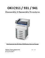
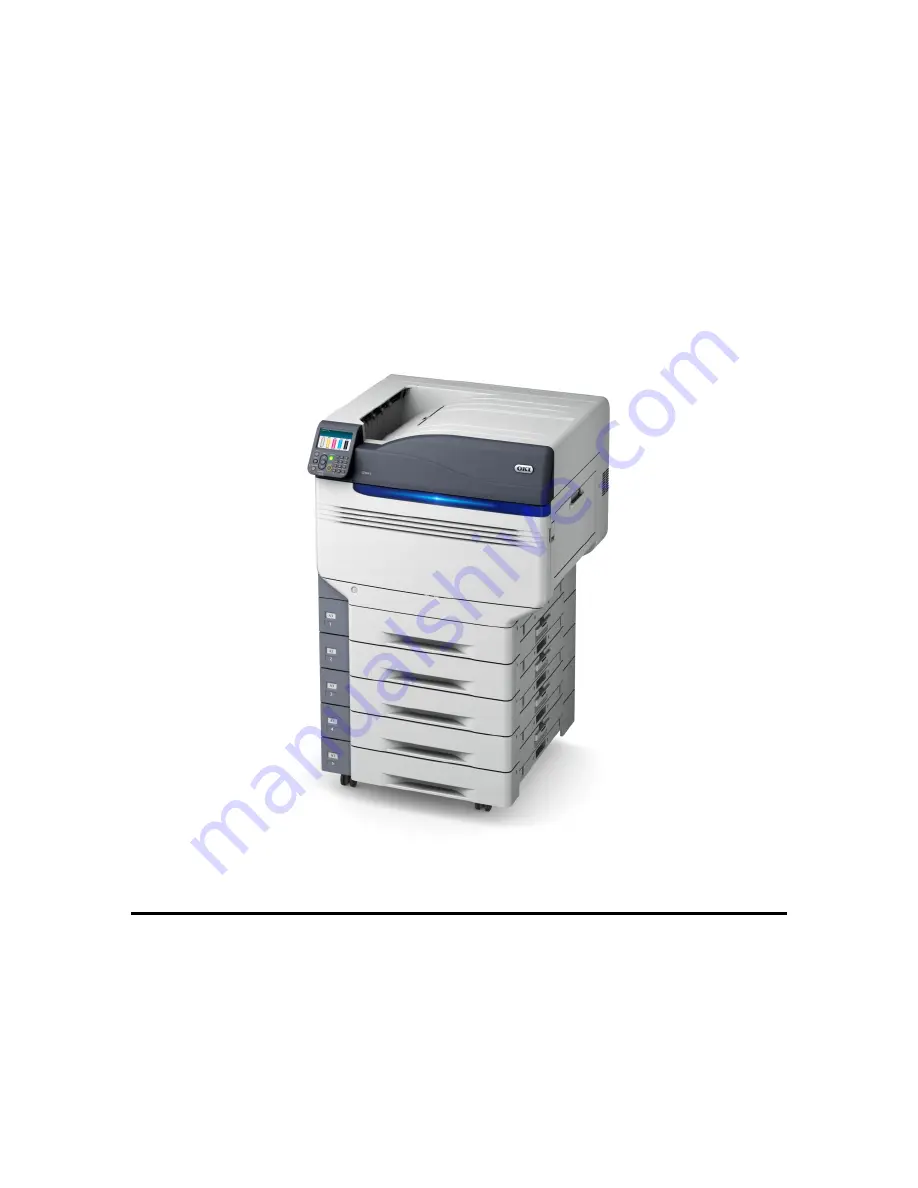
OKI C911 / 931 / 941 

Disassembly & Reassembly Procedures


Distributed at the Oki Data C900 Series Service Classes 


Oki Data Training Department


R

EV

.


1.60 

2000 Bishops Gate Blvd. 
Mt. Laurel, NJ 08054


Summary of Contents for C911 DICOM

Page 1: ...OKI C911 931 941 Disassembly Reassembly Procedures Distributed at the Oki Data C900 Series Service Classes Oki Data Training Department REV 1 60 2000 Bishops Gate Blvd Mt Laurel NJ 08054...

Page 2: ...printers Oki Data assumes that each student has already demonstrated their knowledge of basic electronics troubleshooting disassembly and reassembly of this type of equipment Important Safety Notes Th...

Page 3: ...ion to installing the correct screw color and size If you have leftover screws please return them to the instructors before the printers are re packed Front Left Side Rear Right Side 2 Lift the toner...

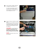
Page 4: ...s handle 4 Open the front door to reveal the installed drums Remove the drums by lifting the front edge and pulling the drum out As you slowly pull the drum out grab the drum as shown to fully remove...

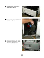
Page 5: ...andle in the middle of the bottle Grab and support the waste toner bottle by this handle to fully remove it from the printer 6 Remove Belt Unit On either side of the belt assembly are blue captive loc...

Page 6: ...ailure to re lock the 2 lock levers prior to closing the front drum door may break the lock levers or the front drum door CAUTION Do Not place the image belt in any position other than horizontal as y...

Page 7: ...pulling the drawer straight out and lifting it slightly 10 Remove toner cover door by removing the 4 black screws and gently lifting and pulling the door away from the printer 11 Remove Operator Pane...

Page 8: ...hen reattaching the operator panel during reassembly If the cable s are disconnected symptoms may be no display and no initialization when powered up 13 Unplug the 2 wire harnesses from the operator c...

Page 9: ...plastic cover 17 Remove lower left cover which is held in by 2 screws and 4 tabs NOTE Metal plate which was removed in the previous step is still present in this picture 18 Remove the low voltage powe...

Page 10: ...ower switch that you must depress to remove the cover Release that tab and gently lift the cover over the lift handle extension on the side and slide off to remove NOTE Some units may have 1 additiona...

Page 11: ...9 Releasing the front offset cover tab 22 Gently release these tabs and remove the offset cover 23 Remove the stacker full lever which is clipped in...

Page 12: ...s 25 Unthread the photo interrupter sensor wiring harness and let hang over the rear of the printer 26 Remove 3 screws securing the job offset into the printer 1 short screw on the top frame and 2 lon...

Page 13: ...11 Front screw securing the job offset mechanism to the printer 27 Gently lift and remove the job offset mechanism...

Page 14: ...the frame 3rd screw is at rear facing down into the frame 29 There are 4 tabs holding the top cover to the toner cartridge separators Disengage the 4 tabs and lift the top cover off 30 Open the paper...

Page 15: ...d pull the drawer out from the printer 32 Lift the blue lock tab and remove the fuser by lifting it straight up 33 Loosen the 9 screws on the rear shield plate slide the shield to the left and slide t...

Page 16: ...able connector from the wire bundles and gently pull it towards the MPT assembly 35 Remove the lift handle from the rear by removing 3 screws and unthreading the wire bundles from the handle assembly...

Page 17: ...g slip a small screw driver in to press and release the 2 tabs on the left side of the lower access cover Remove the access cover 39 Slide the paper guide towards the front of the printer to remove 40...

Page 18: ...16 41 Open the multi purpose paper tray MPT unit 42 Locate the black plastic cover on the side frame...

Page 19: ...t the tab on the black plastic cover as shown in the last photo and slide the plastic cover down and remove it 44 Remove the 4 screws securing the multi purpose tray unit to the printer Be Careful It...

Page 20: ...l the multi purpose tray unit from the printer NOTE The following step is only necessary on the C911 C931 46 Remove the fifth station guard by removing 1 black screw and unclip from the printer frame...

Page 21: ...y removing 1 silver screw and lifting 1 tab on the bottom of the guard CAUTION The tab on the bottom of this guard can be easily broken Gently lift the guard while you are removing it 48 Disconnect 3...

Page 22: ...eft on the left and right drum door hinges arrow callouts Do not remove them just ensure that these are in place during reassembly 50 Gently unclip the left and right side door frames from the front d...

Page 23: ...m the registration sensor NOTE This is a plastic connector that is attached to the printer frame Do Not Stress this connector when unplugging or plugging it in during reassembly 53 Gently release the...

Page 24: ...he metal guide plate 55 On the front of the printer pull the right side door frame down 56 Remove the black plastic cover on the paper guide frame by removing 2 black screws Gently re close the right...

Page 25: ...er frame and 2 more on the rear of the printer frame and remove this assembly 59 From the printer right side remove the black plastic paper guide by removing 2 silver screws and pulling this guide out...

Page 26: ...from the front of the plate and 2 screws from the rear of the plate 63 Make sure the eject assembly drawer is pulled out from the printer Gently lift the registration roller media thickness assembly...

Page 27: ...ter you lift the assembly you will see a 2 wire white cable assembly in the middle of the assembly Unplug this connector and gently remove the roller synchro assembly This is an optical sensor which c...

Page 28: ...or from main board HOP CL Unplug 2 wire red connector from main board REG ICL Unplug 4 wire red connector from main board HOP M 69 Unthread these harnesses from the wire guide frame 70 Slide the hoppi...

Page 29: ...supply motor connector on the sub assembly board NOTE These cables are wrapped around the sub assembly board 74 On the front of the printer locate the 1st station toner block plastic piece to the left...

Page 30: ...ips to be released at the front of the guide assembly NOTE DO NOT SEPARATE THE DUCT ASSEMBLY FROM THE TONER CARTRIDGE GUIDE ASSEMBLY 76 Starting at the left most station yellow in this model and gentl...

Page 31: ...ng for the Op Panel cables as shown below 79 This screw goes through the ground locking collar for one of the Op Panel Cables Do Not Forget to reattach this collar during reassembly 80 There are 10 C9...

Page 32: ...printer frame At this point the duct support tray can be removed 85 The green highlighted area shows the LED Print Head cables and the bend they take to pass through the frame and into the PU CU Boar...

Page 33: ...photos and text below NOTE The LED Print Head cable connectors look like this when the cables are removed Cables are inserted with the locks in the unlocked position and then the tab is gently swung d...

Page 34: ...ill cause errors on power up As you can see the cable at the right has 3 damaged connectors and the only solution is to replace the damaged cable 87 There are 20 wire harness cables to disconnect 88 G...

Page 35: ...33 89 Remove 1 screw securing the USB port to the card cage frame 90 Remove 9 silver screws from the main logic board and gently remove the main logic board...

Page 36: ...ps securing the cable harnesses to the card cage and carefully unthread the cable harnesses from the card cage 92 Unplug the cables in the POW24 cable guide from board F1D 93 Remove the 6 silver screw...

Page 37: ...d cage and gently unthread all wire harnesses 96 Remove the plastic insulator sheet by unsnapping the 3 plastic tabs at the bottom of the insulator sheet 97 Remove 5 black screws and 1 silver screw ho...

Page 38: ...llow access to the screw securing them to the printer NOTE Each motor is held in place by 5 screws and has 2 wire harnesses attached except black which only has one 10 pin wire harness connector 100 O...

Page 39: ...and screws starting at the top and working your way down to the bottom screw 102 On the left side of the printer remove 1 silver screw from the black plastic securing the power switch to the frame Rem...

Page 40: ...upply assembly You Do Not need to remove the cables just reinstall the low voltage power supply 106 Start Reassembly FOLLOW THE DISASSEMBLY DIRECTIONS IN REVERSE TO REASSEMBLE THE PRINTER NOTES for a...

Reviews: