Page: 58
Service Guide ML390/391
Chapter 3 Maintenance & Disassembly
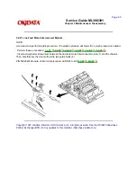
3.2.15 Space Motor Assembly
· Perform these procedures:
3.2.01
, 3.2.03
, 3.2.04
, 3.2.14
.
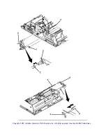
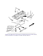
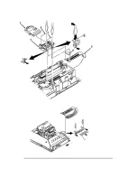
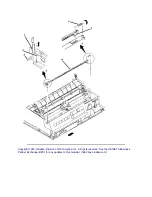
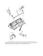
· Note the position of the connector (1). During assembly, the connectors orientation is critical for correct
printhead operation.
· Detach the connector.
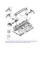
· Remove the three mounting screws (2).
· Remove the space motor assembly (3). Be careful not to lose the slider (4).
NOTES:
Installation
Do not touch the contacts of the assembly.
Position the slider first.
The contact side of the head cable faces down when the carriage cable is inserted into the connector on
the space motor assembly.
Work the cable from side to side until it is fully seated in the connector. No contacts should be visible.
Perform the printhead gap adjustment after installing this assembly.
Refer to Section 3.3 of this Service
Handbook for details
.
Cleaning
When cleaning, refer to Section 3.4 of this Service Handbook
.
Lubricating
When lubricating, refer to Section 3.5 of this Service Handbook
.
P/N 51001801 Guide: Space Motor (Slider) All RSPL A B C
B.2.09
P/N 56719201 Connector: Head All RSPL A B C
B.2.09
P/N 56507104 Motor: Space (Assembly) All RSPL A B C
B.2.09
Summary of Contents for MICROLINE Turbo ML390
Page 49: ...Partner Exchange BPX for any updates to this material http bpx okidata com ...
Page 53: ...Page 29 Service Guide ML390 391 Chapter 2 Principles of Operation ...
Page 81: ......
Page 95: ...Partner Exchange BPX for any updates to this material http bpx okidata com ...
Page 106: ...Partner Exchange BPX for any updates to this material http bpx okidata com ...
Page 110: ......
Page 115: ......
Page 132: ......
Page 222: ......

