Page: 25
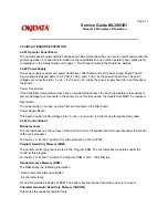
Service Guide ML390/391
Chapter 2 Principles of Operation
2.3.06 Alarm Circuits
Drive Circuit Fault Alarm Circuit
This is a protective circuit which causes the AC line fuse to open when a fault occurs in the printhead drive
circuit, the spacing motor drive circuit, or the line feed drive circuit. The fault alarm circuit monitors the
drive time of each of these circuits and produces the ALM signal if any drive time exceeds its specified
value. The ALM signal activates SCR ON, which causes the secondary coil (40 volts) of the transformer to
short-circuit. This creates an over-current condition, which causes the AC line fuse to open.
Head Overheat Alarm Circuit
The printhead contains a built-in thermistor (rated at 130 degrees Celsius). The thermistor monitors the
printhead temperature.
Printhead temperature rises when the unit is printing. When the temperature of the printhead rises, the
resistance of the thermistor decreases and the potential falls at the negative input of comparator Q7. Q7 is
located on the main controller board.
When printhead temperature reaches approximately 90 degrees Celsius, this comparator output inverts,
causing the HEAD TEMP signal to be sent to the motor control LSI. The unit prints unidirectionally.
When printhead temperature reaches approximately 130 degrees Celsius, the thermistor sends a signal to
the main control board, generating the HEAD OVERHEAT alarm. Printing stops when this alarm is
detected (A BUSY signal is sent to the host computer. Data remains in the print buffer as long as power is
supplied to the printer). This allows the printhead temperature to fall. When the printhead temperature falls
below the alarm detection level, printing is resumed (the BUSY signal to the host computer becomes
inactive).
Paper End Detection Circuit
When the printer runs out of paper, the photosensor on the main control board is deactivated. This causes
the signal PAPER END-N to become low. This signal is fed to pin 55 of the motor control LSI (Q11 on the
main control board). Printing stops and the ALARM lamp lights.
Copyright 1997, Okidata, Division of OKI America, Inc. All rights reserved. See the OKIDATA Business
Partner Exchange (BPX) for any updates to this material. (http://bpx.okidata.com)
Summary of Contents for MICROLINE Turbo ML390
Page 49: ...Partner Exchange BPX for any updates to this material http bpx okidata com ...
Page 53: ...Page 29 Service Guide ML390 391 Chapter 2 Principles of Operation ...
Page 81: ......
Page 95: ...Partner Exchange BPX for any updates to this material http bpx okidata com ...
Page 106: ...Partner Exchange BPX for any updates to this material http bpx okidata com ...
Page 110: ......
Page 115: ......
Page 132: ......
Page 222: ......

