MSM9225B User’s Manual
Chapter 5 Electrical Characteristics
5 – 2
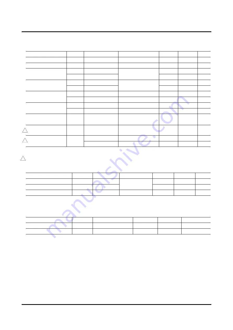
5.1.3 DC Characteristics
(V
DD
= 4.5 to 5.5 V, Ta = –40 to +125°C)
Parameter
Symbol
Applicable pin
Condition
Min.
Max.
Unit
“H” Input Voltage
V
IH
Applies to all inputs
—
0.8V
DD
V
DD
+0.3
V
“L” Input Voltage
V
IL
Applies to all inputs
—
–0.3
+0.2 V
DD
V
I
IH1
XT
3
25
µA
“H” Input Current
I
IH2
Other inputs
V
I
= V
DD
–1.0
+1.0
µA
I
IL1
XT
–25
–3
µA
“L” Input Current
I
IL2
Other input
V
I
= 0V
–1.0
+1.0
µA
V
OH1
INT
,
PRDY
/SWAIT
I
OH1
= –80
µ
A
V
DD
–1.0
—
V
“H” Output Voltage
V
OH2
AD7-0/D7-0
I
OH2
= –400
µ
A
V
DD
–1.0
—
V
V
OL1
INT
,
PRDY
/SWAIT
I
OL1
= 1.6 mA
—
0.4
V
“L” Output Voltage
V
OL2
AD7-0/D7-0
I
OL2
= 3.2 mA
—
0.4
V
Output Leakage
Current
I
IH1
PRDY
/SWAIT
AD7-0/D7-0
V
I
= V
DD
/0 V
–1.0
+1.0
µA
Dynamic Supply
Current
I
DD
—
f
OSC
= 16 MHz, No Load
—
9
mA
—
SLEEP Mode
—
400
µA
Static Supply Current
I
DDS
—
STOP Mode
—
100
µA
5.1.4 Rx0, Rx1 Characteristics
Differential input mode
(V
DD
= 4.5 to 5.5 V, Ta = –40 to
+125°C)
Parameter
Symbol
Applicable pin
Condition
Min.
Max.
Unit
‘dominant’ Input Voltage
VRx0(d)
Rx0
–0.3
VRx1 –0.4
V
‘recessive’ Input Voltage
VRx0(r)
Rx0
VRx1 =
0.4 V
DD
to 0.6 V
DD
VRx1 +0.4
V
DD
+3
V
Input Leakage Current
I
LK
Rx0, Rx1
VR
XI
= V
DD
/0 V
–1
+1
µA
5.1.5 Tx0, Tx1 Characteristics
(V
DD
= 4.5 to 5.5 V, Ta = –40 to
+125°C)
Parameter
Symbol
Condition
Min.
Max.
Unit
“H” Output Voltage
V
OH
I
OH
= –3.0 mA
V
DD
–0.4
—
V
“L” Output Voltage
V
OL
I
OL
= 10.0 mA
—
0.4
V
B
B
B
Summary of Contents for MSM9225B
Page 7: ...Chapter 1 Overview...
Page 13: ...Chapter 2 Register Descriptions...
Page 53: ...Chapter 3 Operational Description...
Page 62: ...Chapter 4 Microcontroller Interface...
Page 71: ...Chapter 5 Electrical Characteristics...
Page 81: ...Appendixes...


