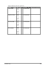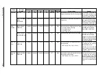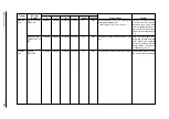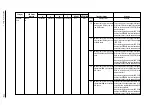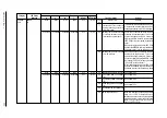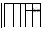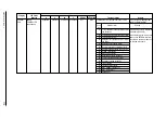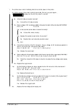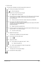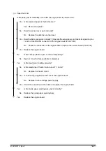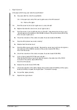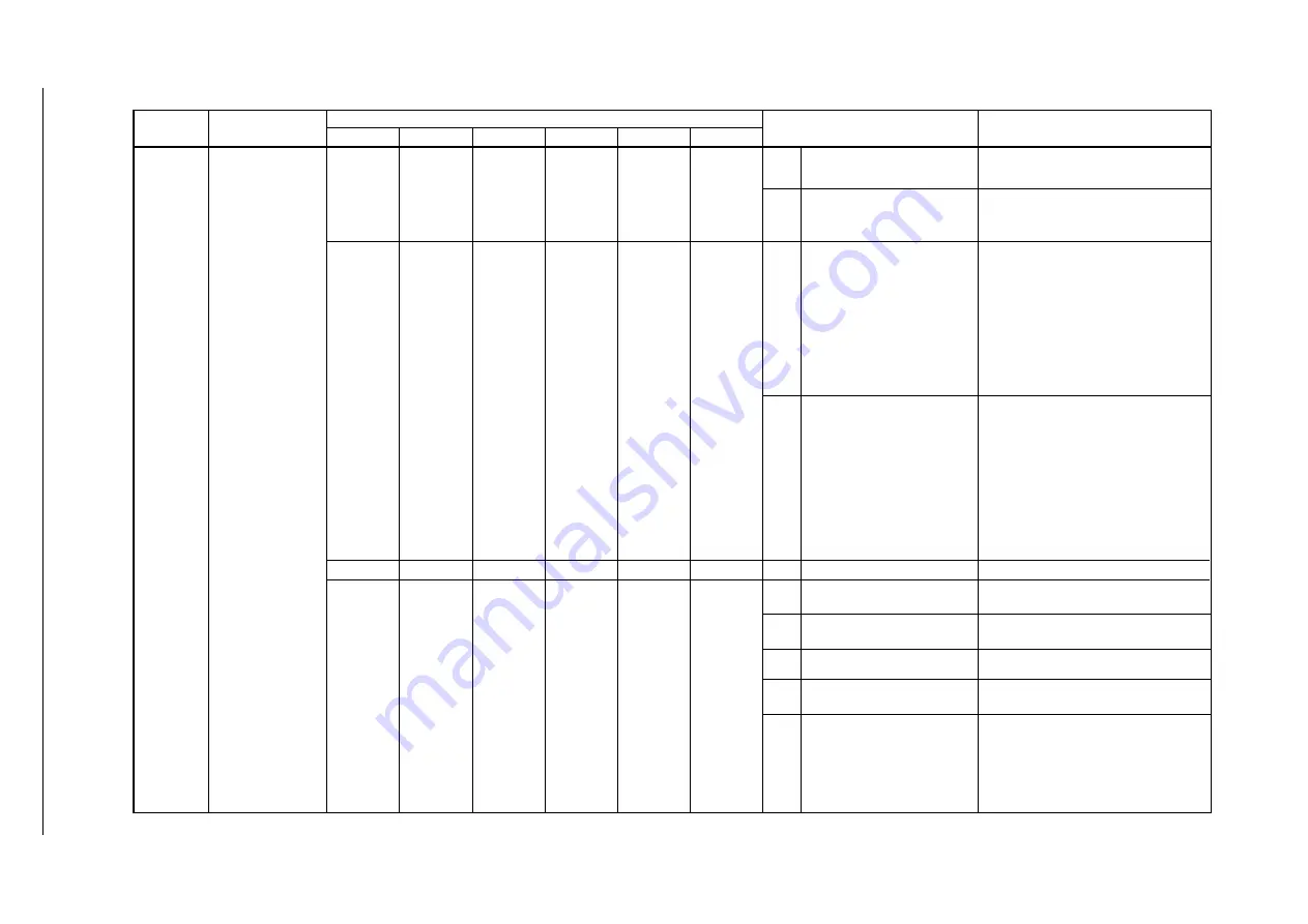
Category LCD Status LED
Message K C M Y READY ATTENTION Trouble or Status Remedy
ERROR
nn
Controller
Error
Details of error
Code
(nn)
Remedy
41057610TH Rev. 1
111
Indicates that Toner sensor is
abnormal when page counter is
below thirty.(alarm)
Indicates that a timeout occurred
on interface between the page
printer and the operator panel.
Indicates that a timeout occurred
on CU-PU interface.
Indicates that the printer overruns.
Cyan Image drum unit up/down
error
Magenta Image drum unit up/down
error
Yellow Image drum unit up/down
error
Black Image drum unit up/down error
temperature sensor error
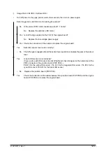
This massage is cleared when the drum is prop-
erly positioned or sensor lever which is ex-
changed correspond to the LED color lights.
77
80
82
92
D6
D7
D8
D9
DA
Blink Blink Blink Blink OFF Blink
Undefined Undefined Undefined Undefined OFF Blink
Blink Blink Blink Blink OFF Blink
Undefined Undefined Undefined Undefined OFF Blink
Make sure that the surrounding temperature
stays -10 < t< 50
°
C. If this condition is not
satisfied, adjust the surrounding temperature,
otherwise satisfied, replace the sensor board
(RXM-PCB), junction board (PXF-PCB) or
engine board (PX4-PCB).
Check the connection between the main
board and the operation panel. Turn on the
power of the page printer again. If this error
still occurs, replace the cable, the main board
(PCE PCB) or the cover assembly operation
panel.
When replacing the main board (PCE PCB),
demount the EEPROM chip from the old main
board and remount it on the new main board.
Check the connection between the main
board and the engine board. Turn on the
power of the page printer again. If this error
still occurs, replace the program ROM of the
main board (PCE PCB) or the engine board
(PX4 PCB), or the board itself.
When replacing the main board (PCE PCB),
demount the EEPROM chip from the old main
board and remount it on the new main board.
See Chapter 6.5.2
See Chapter 6.5.2
See Chapter 6.5.2
See Chapter 6.5.2
Summary of Contents for OKICOLOR 8
Page 2: ...OKICOLOR 8 Color LED Page Printer Maintenance Manual 1999 7 14 Rev 1...
Page 12: ...41057610TH Rev 1 11 This page intentionally left blank...
Page 44: ...41057610TH Rev 1 43 Figure 3 1 3 2 Parts Layout...
Page 45: ...41057610TH Rev 1 44 Figure 3 2...
Page 46: ...41057610TH Rev 1 45 Figure 3 3...
Page 47: ...41057610TH Rev 1 46 Figure 3 4...
Page 105: ...41057610TH Rev 1 104 olor check pattern...
Page 156: ...41057610TH Rev 1 155 Fig 8 2 2 1 O 3 N C 0 9 Q 6 M J 8 7 8 S H E 7 K G 4 P D R L B A F T 5...
Page 166: ...41057610TH Rev 1 165 Fig 8 6 H B E F 2 J 4 4 I 3 3 6 9 8 7 G C D A 0 5 1 5...
Page 168: ...41057610TH Rev 1 167 Fig 8 7 1 2 5 6 3 4...
Page 170: ...41057610TH Rev 1 169 Fig 8 8 7 7 5 A 5 6 6 3 3 4 4 0 9 1 8 2...
Page 172: ...41057610TH Rev 1 171 Fig 8 9 7 6 6 5 5 4 1 8 8 2 3 4 3 7...
Page 196: ...41057610TH Rev 1 195 SEN1 CN22 CN23 CN24 5 2 PCB Layout AOLT PCB...
Page 197: ...41057610TH Rev 1 196 6 PARTS LIST 4 D 9 3 B 6 C A E F 2 J I L 0 1 K G G G 5 7 H 9 8...


