41057610TH Rev. 1
16 /
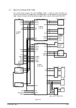
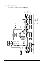
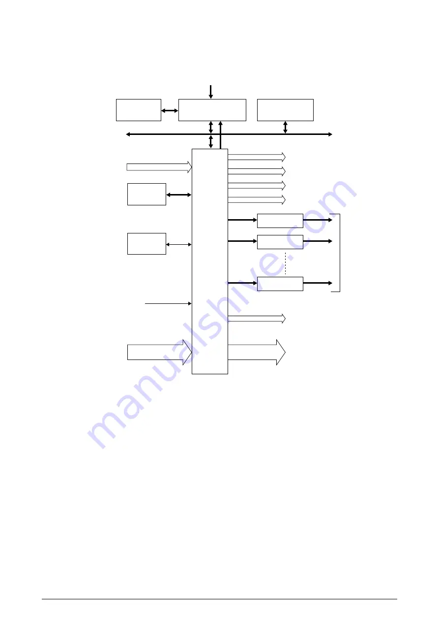
Figure 2.4
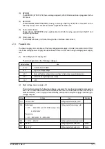
The engine control block (PU) is controlled by the engine control board (PX4 PCB) which consists
of a CPU (MSM65524), general purpose LSI chips, EPROM, EEPROM, pulse motor drivers, and
video memory. (See Figure 2.4.)
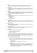
(1) CPU
This is an 8-bit CPU (OKI MSM65524) containing the AD converter and controls the whole
system.
(2) General-purpose LSI
This LSI (MB87D113PFV) is provided in the printer engine control block and has controller-
engine video interface, LED interface, motor control, sensor input, video memory control,
main scanning color correction, skew correction, high-voltage power control, and OST-EX2
functions.
2.2 Engine Control Board (PX4 PCB)
C HEAD I/F (3.3V)
M HEAD I/F (3.3V)
Y HEAD I/F (3.3V)
B HEAD I/F (3.3V)
MT DRIVER
MTD2005F
MT DRIVER
MTD2005F
MT DRIVER
MTD2005F
PULSE MOTOR x 8
LSI
MB87D
113PFV
ANALOG INPUT
(Heater temperatures and environment humidity and temperature)
HIGH-VOLTAGE POWER SUPPLY
SERIAL INTERFACE (2 channels)
GENERAL INPUT PORT
GENERAL OUTPUT PORT
RESET
OSC 28MHz
VIDEO MEM
HM658512
VIDEO I/F
CPU BUS
EEPROM
NM93C66N-NW
ROM
27512
CPU
MSM65524
(containing AD converter)
INT
Summary of Contents for OKICOLOR 8
Page 2: ...OKICOLOR 8 Color LED Page Printer Maintenance Manual 1999 7 14 Rev 1...
Page 12: ...41057610TH Rev 1 11 This page intentionally left blank...
Page 44: ...41057610TH Rev 1 43 Figure 3 1 3 2 Parts Layout...
Page 45: ...41057610TH Rev 1 44 Figure 3 2...
Page 46: ...41057610TH Rev 1 45 Figure 3 3...
Page 47: ...41057610TH Rev 1 46 Figure 3 4...
Page 105: ...41057610TH Rev 1 104 olor check pattern...
Page 156: ...41057610TH Rev 1 155 Fig 8 2 2 1 O 3 N C 0 9 Q 6 M J 8 7 8 S H E 7 K G 4 P D R L B A F T 5...
Page 166: ...41057610TH Rev 1 165 Fig 8 6 H B E F 2 J 4 4 I 3 3 6 9 8 7 G C D A 0 5 1 5...
Page 168: ...41057610TH Rev 1 167 Fig 8 7 1 2 5 6 3 4...
Page 170: ...41057610TH Rev 1 169 Fig 8 8 7 7 5 A 5 6 6 3 3 4 4 0 9 1 8 2...
Page 172: ...41057610TH Rev 1 171 Fig 8 9 7 6 6 5 5 4 1 8 8 2 3 4 3 7...
Page 196: ...41057610TH Rev 1 195 SEN1 CN22 CN23 CN24 5 2 PCB Layout AOLT PCB...
Page 197: ...41057610TH Rev 1 196 6 PARTS LIST 4 D 9 3 B 6 C A E F 2 J I L 0 1 K G G G 5 7 H 9 8...

