41057610TH Rev. 1
17 /
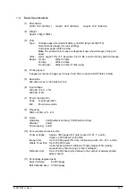
Output voltage
Use
+3.3 V
CU Unit CPU, LED HEAD
+5 V
Logic circuit supply voltage
+32 V
Motor and fan drive voltage and source voltage for high-voltage supply, discharge lamp
+12 V
HSP, OP Amp, high voltage power supply
–12 V
HSP
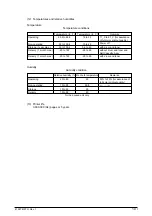
Output
Voltage
Use
Remarks
CH
-1.35 KV
±
50V
Voltage applied to charging roller
DB
Normal paper
Voltage applied to developing roller
Y. M. C : -250V/+300V, -232V/+300V(First paper. Y only)
K : -275V/+300V
Transparency
Y. M. C. : -200V/+300V, K. : -250V/+300V
SB
Y. M. C.K : -650V/0V
Voltage applied to toner supply roller
TR
0 to 4 KV
Voltage applied to transfer roller
Variable
FIX
0 to 2.5 KV
Voltage applied to transfer roller
Variable
(2)
High voltage power supply unit
This circuit generates the following voltages necessary for electro-photographic processing
from +32 V in accordance with the control sequence from the control board. When cover open
state is detected, +32 V supply is automatically interrupted to stop the supply of all the high-
voltage outputs.
2.3
Power/Units
The power supply unit comprises of the low voltage power supply unit which consists of an AC filter
circuit, low voltage power supply circuit and heater driver circuit, and the high voltage power supply
unit.
(1)
Low voltage power supply unit
This circuit generates the following voltages.
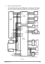
(3)
EPROM
This EPROM (27C512-150) has a storage capacity of 512K bits and stores programs for the
PU block.
(4)
EEPROM
This EEPROM (NM93C66N-NW) having a storage capacity of 4K bits is mounted on the
board by means of IC socket and stores adjustment values etc.
(5)
Pulse motor drivers
These drivers (MTD2005F) drive eight pulse motors for moving up and down the EP and
transferring medium.
(6)
Video memory
This SRAM receives print data through video interface and stores it.
Summary of Contents for OKICOLOR 8
Page 2: ...OKICOLOR 8 Color LED Page Printer Maintenance Manual 1999 7 14 Rev 1...
Page 12: ...41057610TH Rev 1 11 This page intentionally left blank...
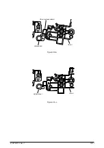
Page 44: ...41057610TH Rev 1 43 Figure 3 1 3 2 Parts Layout...
Page 45: ...41057610TH Rev 1 44 Figure 3 2...
Page 46: ...41057610TH Rev 1 45 Figure 3 3...
Page 47: ...41057610TH Rev 1 46 Figure 3 4...
Page 105: ...41057610TH Rev 1 104 olor check pattern...
Page 156: ...41057610TH Rev 1 155 Fig 8 2 2 1 O 3 N C 0 9 Q 6 M J 8 7 8 S H E 7 K G 4 P D R L B A F T 5...
Page 166: ...41057610TH Rev 1 165 Fig 8 6 H B E F 2 J 4 4 I 3 3 6 9 8 7 G C D A 0 5 1 5...
Page 168: ...41057610TH Rev 1 167 Fig 8 7 1 2 5 6 3 4...
Page 170: ...41057610TH Rev 1 169 Fig 8 8 7 7 5 A 5 6 6 3 3 4 4 0 9 1 8 2...
Page 172: ...41057610TH Rev 1 171 Fig 8 9 7 6 6 5 5 4 1 8 8 2 3 4 3 7...
Page 196: ...41057610TH Rev 1 195 SEN1 CN22 CN23 CN24 5 2 PCB Layout AOLT PCB...
Page 197: ...41057610TH Rev 1 196 6 PARTS LIST 4 D 9 3 B 6 C A E F 2 J I L 0 1 K G G G 5 7 H 9 8...

