41057610TH Rev. 1
28 /
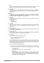
(2)
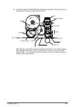
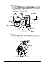
The hopping operation of the front feeder and the up/down operation of the pinch roller 2 are
performed by a single pulse motor, as shown below.
Idle gear A
Hopping roller
From front
One-way clutch gear A
Idle gear B
Cam
One-way clutch gear B
Sensor position
Up/down
Pinch roller
Entrance sensor
Resist roller 2
Form sensor
a
b
When the pulse motor of the front feeder turns right (in the direction of “A”), the front hopping
roller turns left (in the direction of “b”) to drive the cam. This cam moves up and down
the pinch roller 2. The one-way clutch gears are made to turn only in a preset direction by
means of the one-way clutches.
Summary of Contents for OKICOLOR 8
Page 2: ...OKICOLOR 8 Color LED Page Printer Maintenance Manual 1999 7 14 Rev 1...
Page 12: ...41057610TH Rev 1 11 This page intentionally left blank...
Page 44: ...41057610TH Rev 1 43 Figure 3 1 3 2 Parts Layout...
Page 45: ...41057610TH Rev 1 44 Figure 3 2...
Page 46: ...41057610TH Rev 1 45 Figure 3 3...
Page 47: ...41057610TH Rev 1 46 Figure 3 4...
Page 105: ...41057610TH Rev 1 104 olor check pattern...
Page 156: ...41057610TH Rev 1 155 Fig 8 2 2 1 O 3 N C 0 9 Q 6 M J 8 7 8 S H E 7 K G 4 P D R L B A F T 5...
Page 166: ...41057610TH Rev 1 165 Fig 8 6 H B E F 2 J 4 4 I 3 3 6 9 8 7 G C D A 0 5 1 5...
Page 168: ...41057610TH Rev 1 167 Fig 8 7 1 2 5 6 3 4...
Page 170: ...41057610TH Rev 1 169 Fig 8 8 7 7 5 A 5 6 6 3 3 4 4 0 9 1 8 2...
Page 172: ...41057610TH Rev 1 171 Fig 8 9 7 6 6 5 5 4 1 8 8 2 3 4 3 7...
Page 196: ...41057610TH Rev 1 195 SEN1 CN22 CN23 CN24 5 2 PCB Layout AOLT PCB...
Page 197: ...41057610TH Rev 1 196 6 PARTS LIST 4 D 9 3 B 6 C A E F 2 J I L 0 1 K G G G 5 7 H 9 8...

