41057610TH Rev. 1
86 /
3.3.39 PXC PCB
1.
Remove the contact (BL-R) assy and contact (CL-R) assy. (See 3.3.36)
2.
Remove the contact (BL-L) assy and contact (CL-L) assy. (See 3.3.37)
3.
Remove the hopping motor. (See 3.3.19)
4.
Remove the motor assy BT. (See 3.3.15)
5.
Remove the gear heat assy. (See 3.3.12)
6.
Remove the roller assy hopping. (See 3.3.25)
7.
Remove the holder gear toner assy. (See 3.3.30)
8.
Remove the high voltage power supply unit. (See 3.3.33)
9.
Unplug the inlet AC. (See 3.3.16)
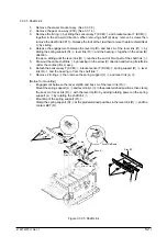
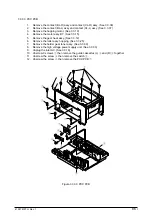
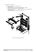
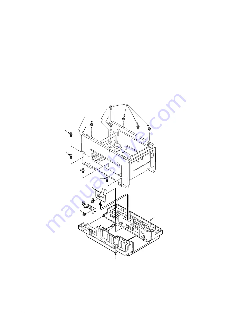
10. Unscrew 9 screws
1
then remove the guide cassettes (L)
2
and (R)
3
together.
11. Unscrew the screw
4
then remove the switch
5
.
12. Unscrew the screw
6
then remove the PXC PCB
7
.
1
1
1
1
1
1
7
6
4
5
2
3
Figure 3.3.39 PXC PCB
Summary of Contents for OKICOLOR 8
Page 2: ...OKICOLOR 8 Color LED Page Printer Maintenance Manual 1999 7 14 Rev 1...
Page 12: ...41057610TH Rev 1 11 This page intentionally left blank...
Page 44: ...41057610TH Rev 1 43 Figure 3 1 3 2 Parts Layout...
Page 45: ...41057610TH Rev 1 44 Figure 3 2...
Page 46: ...41057610TH Rev 1 45 Figure 3 3...
Page 47: ...41057610TH Rev 1 46 Figure 3 4...
Page 105: ...41057610TH Rev 1 104 olor check pattern...
Page 156: ...41057610TH Rev 1 155 Fig 8 2 2 1 O 3 N C 0 9 Q 6 M J 8 7 8 S H E 7 K G 4 P D R L B A F T 5...
Page 166: ...41057610TH Rev 1 165 Fig 8 6 H B E F 2 J 4 4 I 3 3 6 9 8 7 G C D A 0 5 1 5...
Page 168: ...41057610TH Rev 1 167 Fig 8 7 1 2 5 6 3 4...
Page 170: ...41057610TH Rev 1 169 Fig 8 8 7 7 5 A 5 6 6 3 3 4 4 0 9 1 8 2...
Page 172: ...41057610TH Rev 1 171 Fig 8 9 7 6 6 5 5 4 1 8 8 2 3 4 3 7...
Page 196: ...41057610TH Rev 1 195 SEN1 CN22 CN23 CN24 5 2 PCB Layout AOLT PCB...
Page 197: ...41057610TH Rev 1 196 6 PARTS LIST 4 D 9 3 B 6 C A E F 2 J I L 0 1 K G G G 5 7 H 9 8...


