41057610TH Rev. 1
97 /
4.1.3 Engine maintenance mode
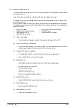
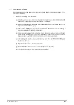
To set the engine maintenance mode, turn on the power switch of
the page printer while pressing on the ENTER and FORM FEED keys. The engine maintenance
mode is set and “ENG MNT” is displayed on-screen.
Note: The engine maintenance mode is hidden and not available to the user.
To exit this mode, press the ONLINE switch. The operation mode is set. The engine maintenance
mode supports the following functions:
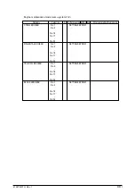
• Head drive time setting (CYAN, MAGENTA, YELLOW, BLACK)
• Drum count display (CYAN, MAGENTA, YELLOW, BLACK)
• Total drum count display (CYAN, MAGENTA, YELLOW, BLACK)
• Fuser count display
• Belt count display
• Oil roller count display
• Setting of standard tray paper feed length
• Setting of second tray paper feed length
• Setting of frontfeeder paper feed length
• Engine reset
(1) Head drive time setting (CYAN, MAGENTA, YELLOW, BLACK)
Sets the time of driving each LED head.
(2) Drum count display (CYAN, MAGENTA, YELLOW, BLACK)
Displays the number of revolutions of each EP drum counted by the engine on the LCD.
(3) Total drum count display (CYAN, MAGENTA, YELLOW, BLACK)
Displays the total number of rotations at each color.
(4) Fuser count display
Displays the total number of pages by Fuser which have been counted by the engine.
(5) Belt count display
Displays the total number of pages by Belt which have been counted by the engine.
(6) Oil roller count display
Displays the counter of the oil roller.
(7) T1 position (Setting of standard tray paper feed length)
Sets a value for correcting the amount of paper feeding of the standard tray.
(8) T2 position (Setting of second tray paper feed length)
Sets a value for correcting the amount of paper feeding of the second tray.
(9) Engine reset
- Resets the contents of all EEPROM areas used by the engine with default values.
- Does not reset the following items:
LED head drive time
Menu level 1
Menu level 2
Operator Panel Menu Disable/Enable
Page Print Disable/Enable
Summary of Contents for OKICOLOR 8
Page 2: ...OKICOLOR 8 Color LED Page Printer Maintenance Manual 1999 7 14 Rev 1...
Page 12: ...41057610TH Rev 1 11 This page intentionally left blank...
Page 44: ...41057610TH Rev 1 43 Figure 3 1 3 2 Parts Layout...
Page 45: ...41057610TH Rev 1 44 Figure 3 2...
Page 46: ...41057610TH Rev 1 45 Figure 3 3...
Page 47: ...41057610TH Rev 1 46 Figure 3 4...
Page 105: ...41057610TH Rev 1 104 olor check pattern...
Page 156: ...41057610TH Rev 1 155 Fig 8 2 2 1 O 3 N C 0 9 Q 6 M J 8 7 8 S H E 7 K G 4 P D R L B A F T 5...
Page 166: ...41057610TH Rev 1 165 Fig 8 6 H B E F 2 J 4 4 I 3 3 6 9 8 7 G C D A 0 5 1 5...
Page 168: ...41057610TH Rev 1 167 Fig 8 7 1 2 5 6 3 4...
Page 170: ...41057610TH Rev 1 169 Fig 8 8 7 7 5 A 5 6 6 3 3 4 4 0 9 1 8 2...
Page 172: ...41057610TH Rev 1 171 Fig 8 9 7 6 6 5 5 4 1 8 8 2 3 4 3 7...
Page 196: ...41057610TH Rev 1 195 SEN1 CN22 CN23 CN24 5 2 PCB Layout AOLT PCB...
Page 197: ...41057610TH Rev 1 196 6 PARTS LIST 4 D 9 3 B 6 C A E F 2 J I L 0 1 K G G G 5 7 H 9 8...

