40838301TH Rev.1
4 - 5
4.3.1
LED Print Head
It is used two kind of head as the LED print head. (208 mm width or 216 mm width)
(1)
Disassembly procedure
a)
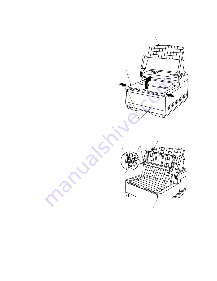
Open the Document Table as-
sembly.
b)
Open the Stacker Cover by push-
ing the Buttons.
c)
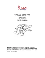
Disconnect the PC connector
from the LED print head.
d)
Disconnect the flat cable from the
PC connector.
e)
Remove the LED print head while
spreading the retainer on the
Stacker Cover.
Note:
Be sure not to touch directly or push the SLA part of the LED print head.
(2)
Reassembly procedure
Reverse the disassembly procedures.
Note:
After replacing the LED print head, set drive time of the LED print head following the marking.
(Refer to section 5.1). When you replace the LED print head, if the width of the LED head
to be used is changed from current version, you should select the head width by the service
personnel initial setting (No. 28). (Refer to table 2.9.1 TF No. 28)
(FX-050VP-C4-001)
Document Guide
Stacker Cover
Buttons
(FX-050VP-C4-002)
Flat cable
PC connector
SLA part
Retainer
LED print head
Stacker Cover
Summary of Contents for OKIFAX 5400
Page 7: ...40838301TH Rev 1 CHAPTER 1 GENERAL INFORMATION...
Page 46: ...40838301TH Rev 1 CHAPTER 2 INSTALLATION PROCEDURE...
Page 130: ...40838301TH Rev 1 CHAPTER 3 BRIEF TECHNICAL DESCRIPTION...
Page 138: ...40838301TH Rev 1 CHAPTER 4 MECHANICAL DISASSEMBLY AND REASSEMBLY...
Page 157: ...40838301TH Rev 1 CHAPTER 5 ADJUSTMENTS...
Page 162: ...40838301TH Rev 1 CHAPTER 6 CLEANING AND MAINTENANCE...
Page 189: ...40838301TH Rev 1 CHAPTER 7 TROUBLESHOOTING AND REPAIR FOR OKIFAX 5400...
Page 240: ...40838301TH Rev 1 CHAPTER 8 DIPSWITCHS SETTING TABLES...
Page 380: ...40838301TH Rev 1 D 2 SECTION 1 CABINET ASSEMBLY 5...
Page 382: ...40838301TH Rev 1 D 4 SECTION 2 CONTROL PANEL ASSEMBLY...
Page 384: ...40838301TH Rev 1 D 6 SECTION 3 PRINTER ASSEMBLY 51...
Page 387: ...40838301TH Rev 1 D 9 SECTION 4 BASE ASSEMBLY 30 37 36 39 40 5...
Page 390: ...40838301TH Rev 1 D 12 SECTION 5 SCAN UNIT...
Page 392: ...40838301TH Rev 1 D 14 SECTION 6 PAPER GUIDE U ASSEMBLY...
Page 394: ...40838301TH Rev 1 D 16 SECTION 7 CABLES 10 11 19 12 20 21...
Page 396: ...40838301TH Rev 1 D 18 SECTION 8 OPTION TELEPHONE US...
Page 399: ...40838301TH Rev 1 D 21 SECTION 8 OPTION TELEPHONE UK ITA NOR DEN BEL...
Page 402: ...40838301TH Rev 1 D 24 SECTION 8 OPTION TELEPHONE HOL GER FRA SWITZ AUT INT L...


