DESCRIPTION OF
PRINT OPERATIONS
40838301TH Rev.1
B - 9
4)
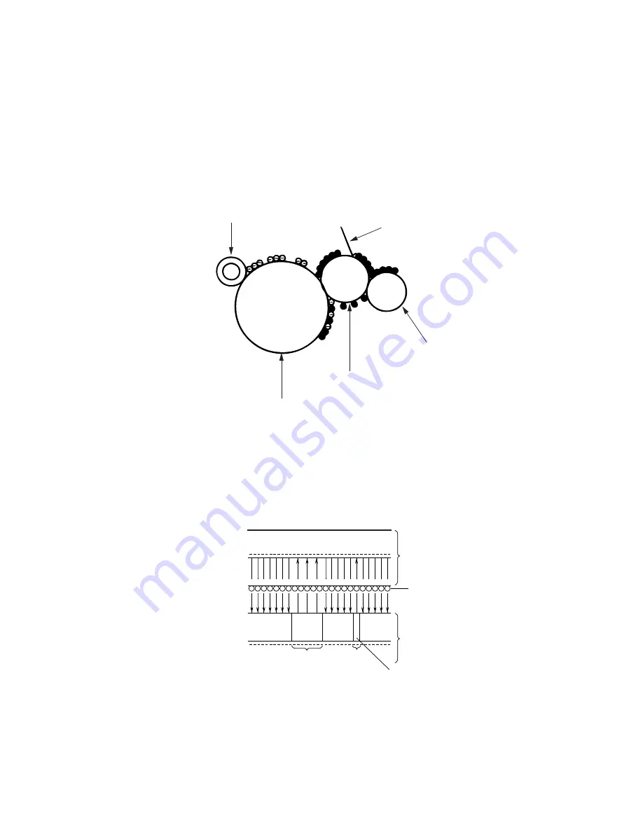
Developing
Toner is attracted to the electrostatic latent image on the EP (image) drum surface to
convert it into a visible toner image. Developing takes place at the contact between the
EP (image) drum and the developing roller.
1
As the toner supply roller rotates while rubbing on the developing roller, a friction
charge is generated between the developing roller and the toner, allowing the
toner to be attracted to the developing roller. (The developing roller surface is
charges positive and the toner, negative.)
-300V
-750V
-100V -750V
-750V
Developing roller
Toner
Image drum
-100V
Exposed
part
Exposed
part
An illustration of activities at the contact point of the
image drum surface and the developing roller (arrow
marks denote the direction of the electric field).
+
–
+
–
+
–
+
–
+
–
+
–
+
–
+
–
+
–
+
–
+
–
+
–
+
–
+
–
+
–
+
–
+
–
+
–
+
–
+
–
+
–
+
–
+
–
+ + + + + + + + + + + + + + + + + + + + + + +
2
The toner attracted to the developing roller is scraped off by the doctor blade,
forming a thin coating of toner on the developing roller surface.
3
Toner is attracted to the exposed part (low-potential part) of the EP (image) drum
at the contact between the EP (image) drum and the developing roller, making the
electrostatic latent image visible.
Doctor blade
Toner supply roller
EP drum
Developing roller
Charge roller
Summary of Contents for OKIFAX 5400
Page 7: ...40838301TH Rev 1 CHAPTER 1 GENERAL INFORMATION...
Page 46: ...40838301TH Rev 1 CHAPTER 2 INSTALLATION PROCEDURE...
Page 130: ...40838301TH Rev 1 CHAPTER 3 BRIEF TECHNICAL DESCRIPTION...
Page 138: ...40838301TH Rev 1 CHAPTER 4 MECHANICAL DISASSEMBLY AND REASSEMBLY...
Page 157: ...40838301TH Rev 1 CHAPTER 5 ADJUSTMENTS...
Page 162: ...40838301TH Rev 1 CHAPTER 6 CLEANING AND MAINTENANCE...
Page 189: ...40838301TH Rev 1 CHAPTER 7 TROUBLESHOOTING AND REPAIR FOR OKIFAX 5400...
Page 240: ...40838301TH Rev 1 CHAPTER 8 DIPSWITCHS SETTING TABLES...
Page 380: ...40838301TH Rev 1 D 2 SECTION 1 CABINET ASSEMBLY 5...
Page 382: ...40838301TH Rev 1 D 4 SECTION 2 CONTROL PANEL ASSEMBLY...
Page 384: ...40838301TH Rev 1 D 6 SECTION 3 PRINTER ASSEMBLY 51...
Page 387: ...40838301TH Rev 1 D 9 SECTION 4 BASE ASSEMBLY 30 37 36 39 40 5...
Page 390: ...40838301TH Rev 1 D 12 SECTION 5 SCAN UNIT...
Page 392: ...40838301TH Rev 1 D 14 SECTION 6 PAPER GUIDE U ASSEMBLY...
Page 394: ...40838301TH Rev 1 D 16 SECTION 7 CABLES 10 11 19 12 20 21...
Page 396: ...40838301TH Rev 1 D 18 SECTION 8 OPTION TELEPHONE US...
Page 399: ...40838301TH Rev 1 D 21 SECTION 8 OPTION TELEPHONE UK ITA NOR DEN BEL...
Page 402: ...40838301TH Rev 1 D 24 SECTION 8 OPTION TELEPHONE HOL GER FRA SWITZ AUT INT L...

