5-48
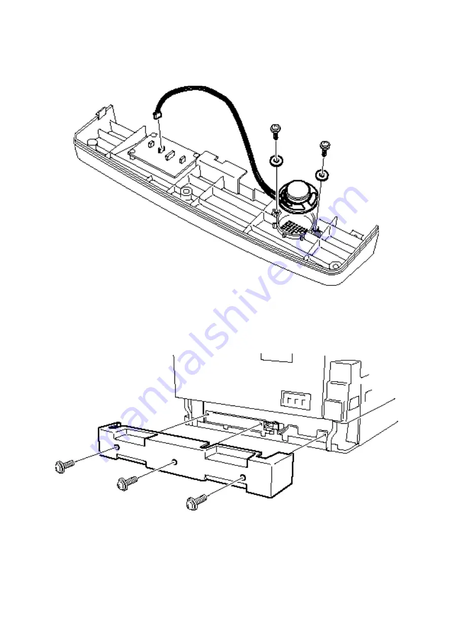
5.55 Speaker
1. Remove the panel lower cover.
2. Remove the connector from the connect B PCB.
3. Remove the two speaker mounting screws, and then remove the speaker.
5.56 Rear cover B
Note: This procedure effects only when optional paper supply unit has been attached.
1. Remove the three rear cover B mounting screws, and then remove the rear cover B.
Summary of Contents for OKIOFFICE 120
Page 7: ...vi ...
Page 17: ...1 10 1 7 Dimensions Dimension in mm ...
Page 23: ...1 16 1 11 ID Label Specification 1 12 Labels location ...
Page 24: ...2 1 Section2 Machine Composition 2 1 Interconnect Block Diagram ...
Page 25: ...2 2 ...
Page 87: ...3 46 Unique Switch F 7 and F 9 Factory use only ...

