2-7
2.5 Sensors
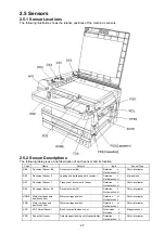
2.5.1 Sensor Locations
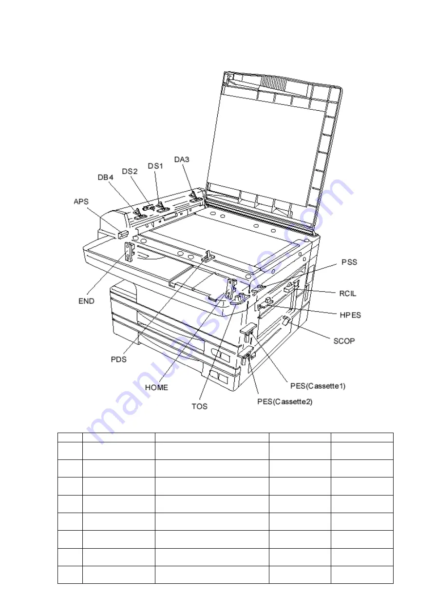
The following illustration shows the relative positions of the machine’s sensors.
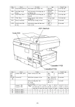
2.5.2 Sensor Descriptions
The following table gives a brief description of each sensor and its function.
Code
Name
Detects
logic
Sensor Type
DB4
Document Sensor B4
Document size (B4)
Detection :L
Not detection :H
Photo interrupter
DS2
Document Sensor 2
Leading and trailing edge of document
Detection :L
Not detection :H
Micro switch
DS1
Document Sensor 1
Presence of document in feeder
Detection :L
Not detection :H
Photo interrupter
DA3
Document Sensor A3
Document size (A3)
Detection :L
Not detection :H
Photo interrupter
HOME
Mirror carriage home
position sensor
Mirror carriage position
Detection :H
Not detection :L
Photo interrupter
END
Mirror carriage end
position sensor
Mirror carriage position
Detection :H
Not detection :L
Photo interrupter
APS
ADF Permit Sensor
Book cover quite close or not
Quite close :L
Not close :H
Magnet sensor
PSS
Paper Set Sensor
Detects paper feeding out of cassette/tray.
Detection: L
Not detection: H
Photo interrupter
Summary of Contents for OKIOFFICE 120
Page 7: ...vi ...
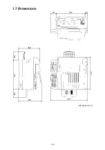
Page 17: ...1 10 1 7 Dimensions Dimension in mm ...
Page 23: ...1 16 1 11 ID Label Specification 1 12 Labels location ...
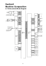
Page 24: ...2 1 Section2 Machine Composition 2 1 Interconnect Block Diagram ...
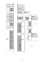
Page 25: ...2 2 ...
Page 87: ...3 46 Unique Switch F 7 and F 9 Factory use only ...


