5-8
5.3.12 Upper Cover Unit
(1) Paper Sensor assembly and Bottom Cover
Release snap-in fingers of Paper Sensor Asm. by a straight screwdriver, then can separate
Paper Sensor Asm. and Bottom Cover.
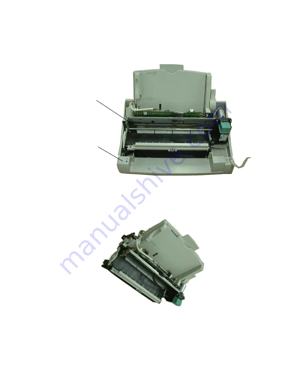
5.3.13 Printer Mode Unit
Figure 5-7 Printer Mode Unit
(1) Printer Mode Asm. & Bottom Cover Unit
Loosen 4 pieces of M3X8 tapping screw then Printer Mode Asm. can be taken out form
Bottom Cover Unit.
5.3.14 Printer Mode Asm.
Figure 5-8 Printer Mode Asm.
(1) Ground Wire
Loosen 1 piece of M3X6 tatite screw for fixing ground wire by a cross screwdriver then
ground wire can be taken out from Printer Bar.
(2) Loosen 2 pieces of M3X10 tapping cap screw on right and left side of Paper Feeder Unit
Printer Mode
Asm.
Bottom Cover
Unit
Summary of Contents for TF-300P
Page 1: ...I TF 300P Field Service Manual Ver 02 July 8 1999 TTIC...
Page 12: ...1 7 1 3 General Appearance 1 3 1 Appearance 1 3 2 Show the operation panel...
Page 84: ...7 23 Check the status of C24 C25 C26 R32 R34 L11 and L12 Check the Microphone inside handset...
Page 100: ...9 1 9 MECHENICAL DRAWING AND PARTS LIST...
Page 101: ...9 2...
Page 102: ...9 3...
Page 103: ...9 4...
Page 104: ...9 5...
Page 105: ...9 6...
Page 106: ...9 7...
Page 107: ...9 8...
Page 108: ...9 9...
Page 109: ...9 10...
Page 110: ...9 11...
Page 111: ...9 12...
Page 112: ...9 13...
Page 113: ...9 14...
Page 114: ...9 15...
Page 115: ...9 16...
Page 116: ...10 1 10 CIRCUIT DRAWING...
Page 117: ...10 2...
Page 118: ...10 3...
Page 119: ...10 4...
Page 120: ...10 5...
Page 121: ...10 6...
Page 122: ...10 7...
Page 123: ...10 8...
Page 124: ...10 9...
Page 125: ...10 10...
Page 126: ...10 11...
Page 127: ...10 12...
Page 128: ...10 13...
Page 129: ...10 14...
Page 130: ...10 15...
Page 131: ...10 16...
Page 132: ...10 17...
Page 133: ...10 18...
Page 134: ...10 19...
Page 135: ...10 20...
Page 136: ...10 21...
Page 137: ...10 22...


