Page: 17
Service Guide OF2200/2400/2600
Chapter 1 Principles of Operation
1.2 TRANSMITTER THEORY OF OPERATION
1.2.01 Typical Transmission
When a telephone number is dialed through the machine (either manually or through auto-dial), a
connection will be established with the receiving station through the Public Switched Telephone Network
(PSTN). When the call is answered, the operator will hear the Called Equipment Device (CED) tone from
the receiving station. With CED received, the transmit machine acknowledges that the connection is
established and proceeds to the CCITT T.30 300 bps handshake procedure.
NOTE:
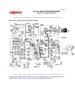
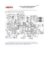
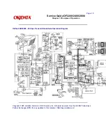
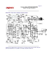
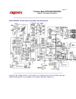
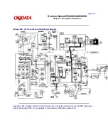
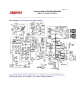
Refer to the Receive and Transmit Handshake Procedure Block Diagrams for functional overviews of 300
bps handshaking.
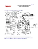
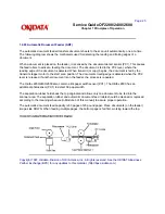
Refer to the Transmit Block Diagram for an overview of G3 Transmit Operations
When the Digital Identification Signal (DIS) is received, G3 mode transmission is possible and the
document is scanned, page by page. The image data is temporarily stored in First In First Out (FIFO)
memory until it becomes valid for transmission. In approximately three seconds, the machine will receive
Called Subscriber Identification (CSI) from the distant station. After reading the document pages and
storing the image data in memory, the machine begins the handshake with the distant station. If the
14.4/9.6 kbps training is successfully completed, the machine will start transmitting the image data in
digital, coded form. Training is a high speed data pattern transmitted to the receive modem. This training
data pattern causes the receive modem to synchronize with the transmit modem. If the training fails due to
bad phone line conditions, an automatic fallback to a lower rate will occur. The result will be indicated on
the LCD display. As the machine transmits each page of image data, the page count on the LCD display
will increment.
Training performs the functions listed below.
· Training tests the line condition for valid transmissions at a particular data rate. The TCF consists of
100 binary zeroes transmitted in a burst. At least 98% accuracy must be achieved before transmission
can take place at that data rate.
· The receiving station uses training to set the preliminary equalization for the current line conditions.
Copyright 1997, Okidata, Division of OKI America, Inc. All rights reserved. See the OKIDATA Business
Partner Exchange (BPX) for any updates to this material. (http://bpx.okidata.com)
Summary of Contents for OF2200
Page 87: ...Partner Exchange BPX for any updates to this material http bpx okidata com...
Page 255: ...Page 151 Service Guide OF2200 2400 2600 Chapter A Board Diagrams A 2 INDEX TO CHARTS...
Page 256: ......
Page 259: ......
Page 262: ......
Page 265: ......
Page 268: ......
Page 273: ......
Page 276: ......
Page 279: ......
Page 284: ...Partner Exchange BPX for any updates to this material http bpx okidata com...
Page 285: ...Page 162 Service Guide OF2200 2400 2600 Chapter A Board Diagrams Okifax 2200 1 of 5...
Page 286: ......
Page 288: ...Page 163 Service Guide OF2200 2400 2600 Chapter A Board Diagrams Okifax 2200 2 of 5...
Page 289: ......
Page 291: ...Page 164 Service Guide OF2200 2400 2600 Chapter A Board Diagrams Okifax 2200 3 of 5...
Page 292: ......
Page 297: ......
Page 299: ...Page 168 Service Guide OF2200 2400 2600 Chapter A Board Diagrams Okifax 2400 2600 2 of 6...
Page 300: ......
Page 302: ...Page 169 Service Guide OF2200 2400 2600 Chapter A Board Diagrams Okifax 2400 2600 3 of 6...
Page 303: ......
Page 307: ...Page 172 Service Guide OF2200 2400 2600 Chapter A Board Diagrams Okifax 2400 2600 6 of 6...
Page 308: ......
Page 317: ......
Page 320: ......
Page 323: ......
Page 326: ......
Page 329: ......
Page 333: ......
Page 337: ......
Page 340: ......
Page 344: ......
Page 348: ......
Page 352: ......
Page 355: ......
Page 359: ......
Page 363: ......
Page 367: ......
Page 371: ......
Page 374: ......
Page 380: ......
Page 387: ...Page 199 Service Guide OF2200 2400 2600 Chapter B Illustrated Parts...
Page 389: ...Page 200 Service Guide OF2200 2400 2600 Chapter B Illustrated Parts...
Page 391: ...Page 201 Service Guide OF2200 2400 2600 Chapter B Illustrated Parts...
Page 395: ...Page 202 Service Guide OF2200 2400 2600 Chapter B Illustrated Parts UST500...

