1.5.05 Exposing
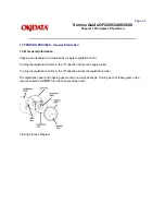
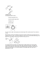
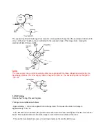
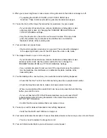
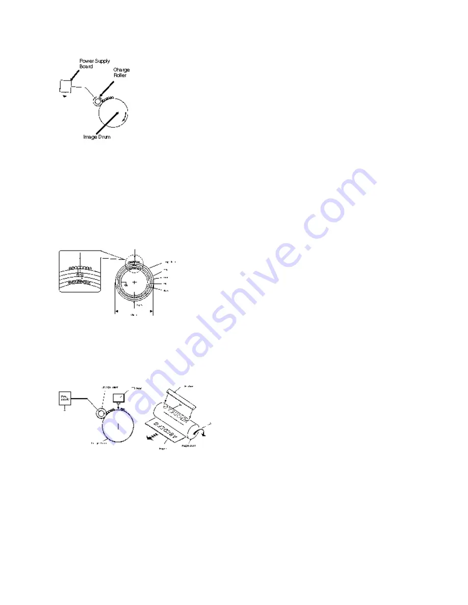
The image drum has four layers.
· Carrier Transfer Layer (CTL)
· Carrier Generation Layer (CGL)
· Underlayer (UL)
· Aluminum Base
The CTL and CGL make up the organic photo conductor layer (OPC), which is about 20 micrometers (m
m) thick.
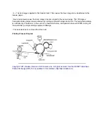
When light from the LED head irradiates the image drum surface, the light energy generates positive and
negative carriers in the CGL. The positive carriers are moved to the CTL by an electrical field acting on the
image drum. The negative carriers flow into the aluminum layer (ground).
The positive carriers moved to the CTL combine with the negative charges on the image surface
(accumulated by the contact charge of the charge roller), lowering the potential on the image drum
surface. The resultant drop in the potential of the irradiated part of the image drum surface forms an
electrostatic latent image on it. The surface potential on this irradiated part of the image drum is
approximately -100 vdc.
Summary of Contents for OF2200
Page 87: ...Partner Exchange BPX for any updates to this material http bpx okidata com...
Page 255: ...Page 151 Service Guide OF2200 2400 2600 Chapter A Board Diagrams A 2 INDEX TO CHARTS...
Page 256: ......
Page 259: ......
Page 262: ......
Page 265: ......
Page 268: ......
Page 273: ......
Page 276: ......
Page 279: ......
Page 284: ...Partner Exchange BPX for any updates to this material http bpx okidata com...
Page 285: ...Page 162 Service Guide OF2200 2400 2600 Chapter A Board Diagrams Okifax 2200 1 of 5...
Page 286: ......
Page 288: ...Page 163 Service Guide OF2200 2400 2600 Chapter A Board Diagrams Okifax 2200 2 of 5...
Page 289: ......
Page 291: ...Page 164 Service Guide OF2200 2400 2600 Chapter A Board Diagrams Okifax 2200 3 of 5...
Page 292: ......
Page 297: ......
Page 299: ...Page 168 Service Guide OF2200 2400 2600 Chapter A Board Diagrams Okifax 2400 2600 2 of 6...
Page 300: ......
Page 302: ...Page 169 Service Guide OF2200 2400 2600 Chapter A Board Diagrams Okifax 2400 2600 3 of 6...
Page 303: ......
Page 307: ...Page 172 Service Guide OF2200 2400 2600 Chapter A Board Diagrams Okifax 2400 2600 6 of 6...
Page 308: ......
Page 317: ......
Page 320: ......
Page 323: ......
Page 326: ......
Page 329: ......
Page 333: ......
Page 337: ......
Page 340: ......
Page 344: ......
Page 348: ......
Page 352: ......
Page 355: ......
Page 359: ......
Page 363: ......
Page 367: ......
Page 371: ......
Page 374: ......
Page 380: ......
Page 387: ...Page 199 Service Guide OF2200 2400 2600 Chapter B Illustrated Parts...
Page 389: ...Page 200 Service Guide OF2200 2400 2600 Chapter B Illustrated Parts...
Page 391: ...Page 201 Service Guide OF2200 2400 2600 Chapter B Illustrated Parts...
Page 395: ...Page 202 Service Guide OF2200 2400 2600 Chapter B Illustrated Parts UST500...

