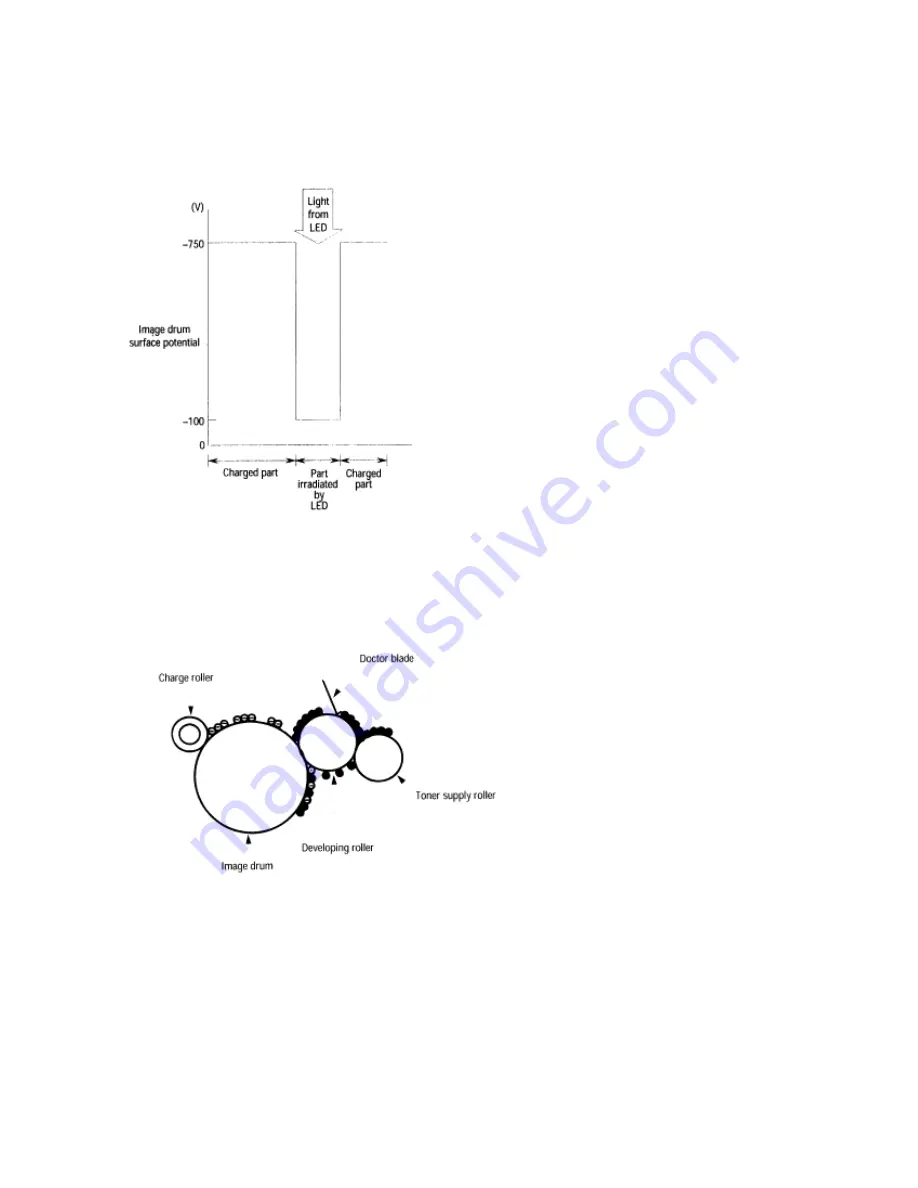
The positive carriers moved to the CTL combine with the negative charges on the image drum surface
accumulated by the contact charge of the charge roller, lowering the potential on the image drum surface.
The resultant drop in the potential of the irradiated portion of the image drum surface forms an
electrostatic latent image on it. The irradiated portion of the image drum surface is kept to about -100 V.
Developing
Toner is attracted to the electrostatic latent image on the image drum surface, converting it into a visible
toner image. Developing takes place through the contact between the image drum and the developing
roller.
As the toner supply roller rotates while rubbing on the developing roller, a friction charge is generated
1.
between the developing roller and the toner, allowing the toner to be attracted to the developing roller
(the developing roller surface is charged positive and the toner, negative.
The toner attracted to the developing roller is scraped off by the doctor blade, forming a thin coat of
2.
toner on the developing roller surface.
Toner is attracted to the exposed portion (low-potential part) of the image drum at the
3.
contact of the image drum and the developing roller, making the electrostatic latent image visible
Summary of Contents for Okipage6e
Page 6: ...Table of Contents Page 6 PARTS LIST 156...
Page 9: ...Partner Exchange BPX for any updates to this material http bpx okidata com...
Page 11: ...4 High Capacity Second Paper Feeder 5 Multi Purpose Feeder...
Page 62: ...Partner Exchange BPX for any updates to this material http bpx okidata com...
Page 67: ...Partner Exchange BPX for any updates to this material http bpx okidata com...
Page 79: ...Partner Exchange BPX for any updates to this material http bpx okidata com...
Page 115: ...Page 63 Service Guide OKIPAGE6e Chapter 6 Troubleshooting Procedures...
Page 118: ...Page 65 Service Guide OKIPAGE6e Chapter 6 Troubleshooting Procedures...
Page 135: ...Page 81 Service Guide OKIPAGE6e Chapter 7 Wiring Diagram...
Page 143: ...Page 83 Service Guide OKIPAGE6e Chapter 7 Wiring Diagram...
Page 166: ......


