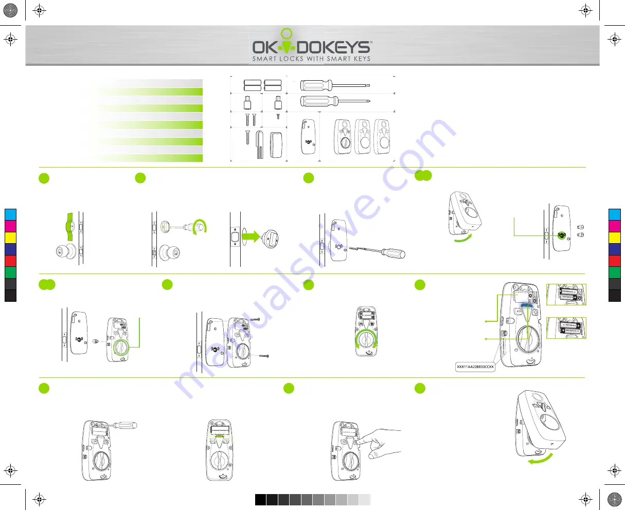
PARTS LIST:
10
1
(x4) AAA Batteries
2
(x1) D-shaped Key Cylinder Spindle Adapter
3
(x1) Flat Key Cylinder Spindle Adapter
4
(x2) Long Phillips-head Screws
5
(x1) T-10 (Torx) Screw
6
(x1) Sensor Kit (Screw, Sensor, Magnet)
7
(x1) T-10 (Torx) Screwdriver
8
(x1)
Reversible
(Phillips/Flathead) Screwdiver
9
(x1) Metal Plate and Rubber Gasket
10
(x1) Smart-Lock and optional covers
1
10
9
2
4
7
8
3
5
6
Technical Support:
support@okidokeys.com | 888-853-2309
Learn More:
www.okidokeys.com
Register and Sign In:
portal.okidokeys.com
8
9
7
6
2
5
Align the Smart-Lock to the spindle adapter.
Insert and tighten one phillips-head screw into the
top-left hole in the Smart-Lock.
Insert and tighten one phillips-head screw into the
bottom-right hole in the Smart-Lock.
Select the appropriate
adapter to match the
existing spindle.
Remove the Smart-Lock
cover.
Align and insert the adapter to
the magnetic hole in the rear of
the Smart-Lock.
4.1
4.2
Thumb turn
should be
vertical
Remove the
two screws
from
the existing interior deadbolt.
Note
: Place the screws in
a safe location. You will
need them during Step 3.
Remove the interior thumb-turn.
Ensure the
deadbolt is retracted
inside the door
before removing the
thumb-turn.
Apply tape to the outside key
cylinder.
Note
: This keeps the key
cylinder on the door
while you install the
Smart-Lock.
1
3
Align the Smart-Lock metal plate and
rubber gasket against the door.
Insert the
two screws
from Step 2
through the two lower holes.
Tighten the screws into the external
key cylinder.
Use the Smart-Lock metal thumb-turn
to lock and unlock the deadbolt.
Ensure the deadbolt moves freely
and engages completely into the
door frame.
Note:
Test your metal key in the
outside key cylinder.
Take a picture or write
down the 17-character
serial number on the
side sticker. This will be
used to register your
lock online.
Install the four AAA
batteries.
A light will appear for
eight seconds to
indicate power up.
Use provided screwdriver to press the
button for 3 sec to launch the Smart-Lock
auto-learning process. The Smart-Lock
will cycle through a series of movements
to learn about your deadbolt and
optimize future locking / unlocking.
Choose the cover that
best compliments your
door or existing
hardware.
Replace the Smart-Lock
cover.
A green light will flash three times to indicate
successful alignment.
This aligns your lock to the correct direction
of locking and unlocking the deadbolt. If
unsuccessful, try again.
After a 5 sec. pause, the Smart-lock is ready
to test.
• The
+
button will move the bolt to the right.
• The
–
button will move the bolt to the left.
Note:
Installation continues on back.
1
2
C
M
Y
CM
MY
CY
CMY
K
Smart-Lock Installation Guide V10.pdf 2 11/4/2014 12:05:48 PM


