
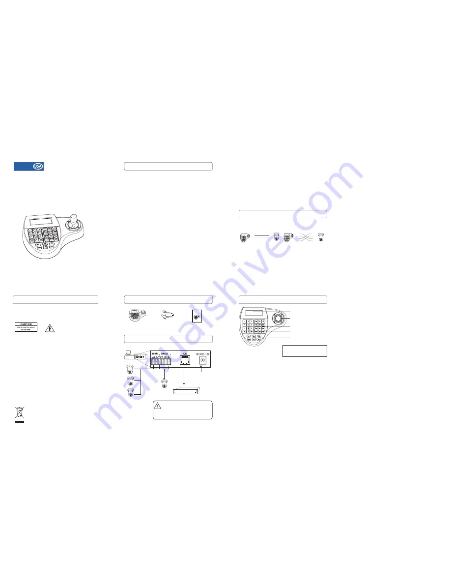
Operation
LCD
Display
Digit Keys
3 Axis Joystick
Camera
Function keys
Function Keys
C a m I D : 0 0 1
M o n I D : 0 0 1
P r o t o c o l :
B a u d r a t e : 9 6 0 0 b p s
B01
I
nitial Screen
PT Operation with Joystick
Zoom operation
Cam ID:
Current camera ID
Mon ID:
Protocol:
Baudrate:
Current monitor ID, indicates the ouput setting on matrix.
Telemetric protocol setting.
Baud-Rate setting
The LCD back-light will be turned off automatically after 15 seconds of
idle time.
Move the joystick up, down, left and right to perform pan or tilt
operation. Depends on the angle of stick, the keyboard changes the
speed of PT movement. On performing the PT action, the LCD will
show the current movement with arrow signs
The keyboard provides camera function keys with following function:
Wide / Tele: Zoom-out and zoom-in
Far / Near: Manual focus control
Open / Close: Manual Iris control
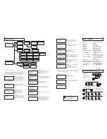
RS-485 (A+/ B-)
For connection to PTZ, Speed-Domes or other device which support
telemetric controling with RS-485 interface. The max. Distance can be up to
1000 meter ( depends on cable and environmental condition).
RS-422 (T+/T-/R+/R-)
RJ-45
DC Power Input
Rs422 Inteface for telemetric control, up to 1200 meters.
Control interface forr matrix device(e.g. Pelco Cm6700,CM6800).
Power supply for the keyboard, Voltage range is 9V to 12V in DC or AC
without polarity( auto-sensing). When connecedt to the Matrix, the keyboard
can be powered thourgh the RJ-45 Interface.
Please make sure that the following chapters are set correctly:
Cable Connection:
Make sure that the RS485/422 cable are connected
correctly to the camera devices.
Baud-Rate:
Protocol:
Camera ID
The keyboard and the camera devices must have the same
baud-rate setting, in order to establish the data exchange. Available settings
are 2400, 4800 and 9600 Bps. For settings on the camera device, please
refer to camera’s manual for further details.
Make sure that the keyboard and camera devices are set with the
same protocol. Currently Pelco and B01/B02 are supported by the
keyboard.please refer to camera’s manual for details.
: Make sure that every connected PTZ device is assigned with
an unique ID.
For settings of your keyboard. Please refer to later chapters for details
B(+)
TX(+)
RX(-)
TX(-)
RX(+)
TX(+)
RX(-)
TX(-)
RX(+)
B(+)
A(+)
A(+)
2
2
4
-
S
R
5
8
4
-
S
R
Check list
Matrix related functions
Switching the input channel.
Auto switching sequence
Open matrix configuration menu
Confirm changes
Change target monitor
Press [PREV] : switch to previous channel
Press [NEXT] : switch to next channel
Press [PREV] for 2 sec.: Sequence in rev. order
Press [NEXT] for 2 sec.: Sequence to next channel.
Press [STOP] to stop the sequencel.
Press [SHIFT] + [SET] to enter the menu and show on main
monitor. For the menu details, please refer to the users manual of
the matrix.
Press [ENTER] after every changes in the menu.
Press [n] + [MON] to change the selected device in the matrix.
PTZ related functions
With the keyboard, you can activate or setup the integrated function of
connected camera device. For the supported functions, please refer to
camera’s manual for further details.
Press [n] + [CAM] : n.. ID of the camera
Move the PTZ to the desired position and press
[SET]+ [n] + [PRESET]
To store the current position as a preset n
To recall the memorized preset position, press
[n] + [PRESET]
N.... The number of preset to be recalled.
You need to enter the keyboard’s menu to setup the tour. Pleare
refer to the later chapter for setup.
To start the tour, press
[n] + [TOUR]
N.. Number of the stored tour
Scan between 2 pre-defined points. To define the points, move to
the left end and press [SET]+[1] + [SCAN], and move to the right
end and press [SET] +[2]+ [SCAN] to store the position.
For changing the scan speed, you need to enter the PTZ’s OSD
menu. Please refer to the users manual for details.
Press [1]+[SCAN] to start the scan procedure.
The pattern function records user’s PTZ movement, and can be
recalled when need. Depends on the camera device, the
recording time and supported number of pattern tracks might
differ. To start the recording procedure, press
[SET] + [n] + [PATTERN]. n....the number of pattern track.
To stop the pattern recording, press
[SET] + [0] + [PATTERN]
To activate the recorded pattern, press
[N] + [PATTERN]
Change currently selected camera
Set / define a Preset position
Recall / activate Preset position
Set Tour function (B01)
Recall / activate Tour
Setup 2-Points scan
Start 2-Points Scan
Start / Stop Pattern recording
Activate recorded Pattern
- Refer all work related to the installaion of this product to qualified
service personnel or system installers.
- Do not attemp to disassemble the keyboard
- Handle the keyboard with care.
- Do not operate the apliance beyond its specified temperature,
humidity or power source ratings.
- Read this user's manual carefully before operation.
To prevent electric shock,
do not remove screws or cover. There are no user-serviceable parts
inside. Contact qualified service personnel for maintenance
Do not strike or shake, as this may
damage the keyboard. It should be protected against extreme pressure,
vibration and humidity during transportation, storage and operation.
Damages caused by improper transportation avoid the warranty.
Do not use the keyboard in an
extreme environment where high temperature or high humidity exists.
Use it within -5°C to +40°C(23°F to 140°F) and a humidity below 90%.
The input power source is 12V DC, and requires at least 500mA.
Make sure that
local electric safty standards are followed when using or installing the
keyboard.
- Do not install this Product in a flammable and explosive
environment.
Before installation and mentainence, make sure that the keyboard is
disconnected from the power source.
Do not install or operate the keyboard near any high-voltage devices
or high-voltage cable.
This product should be operated indoor only.
-
-
The safety distance should remain at least 50 m.
-
Before Starting
Technical specifications are subjects to change without prior notice. This
Manual may contain printing or clerical errors. All trademarks mentioned
belong to their respective owners.
1 X Controller
1x User Manual
AC-DC Power
Supply (optional)
Connection
USER'S MANUAL
Programmable
Keyboard Controller
Matrix
Power
Input
Matrix
Interface
RS-485
up to 32 Devices
RS-422
Interface
DO NOT CONNECT THE RJ-45 PORT
TO ANY COMPUTER NETWORK
INTERFACE,
as this may cause serious
damage to the keyboard.
Unpacking
3-Axis Compact
Keyboard Controller
User's Manual
Warning
TO REDUCE THE RISK OF FIRE OR ELECTRIC SHOCK, DO NOT EXPOSE THIS
PRODUCT TO RAIN OR MOISTURE. DO NOT INSERT ANY METALLIC OBJECTS
THROUGH THE VENTILATION GRILLS OR OTHER OPENINGS ON THE EQUIPMENT.
FCC COMPLIANCE STATEMENT
CE COMPLIANCE STATEMENT
CAUTION: CHANGES OR MODIFICATIONS NOT EXPRESSLY APPROVED BY THE PARTY
RESPONSIBLE FOR COMPLIANCE COULD VOID THE USERS‘S AUTHORITY TO OPERATE THE
EQUIPMENT.
FCC INFORMATION: THIS EQUIPMENT HAS BEEN TESTED AND FOUND TO COMPLY WITH THE
LIMITS FOR A CLASS A DIGITAL DEVICE, PURSUANT TO PART 15 OF THE FCC RULES. THESE
LIMITS ARE DESIGHEND TO PROVIDE REASONABLE PROTECTION AGAINST HAMRFUL
INTERFERENCE WHEN THE EQUIPMENT IS OPERATED IN A COMMERCIAL ENVIRONMENT. THIS
EQUIPMENT GENERATES, USES, AND CAN RADIATE RADIO FREQUENCY ENGERGY AND IF NOT
INSTALLED AND USED IN ACCORDANCE WITH THE INSTRUCTION MANUAL, MAY CAUSE HARMFUL
INTERFERENCE TO RADIO COMMUNICATIONS. OPERATION OF THIS EQUIPMENT IN A
RESIDENTIAL AREA IS LIKELY TO CAUSE HARMFUL INTERFERENCE IN WHICH CASE THE USER
WILL BE REQUIRED TO CORRECT THE INTERFERENCE AT HIS OWN EXPENSE.
WARNING: THIS IS A CLASS A PRODUCT. IN A DOMESTIC ENVIRONMENT THIS PRODUCT MAY
CAUSE RADIO INTERFERENCE IN WHICH CASE THE USER MAY BE REQUIRED TO TAKE ADEQUATE
MEASURES.
CAUTION: TO REDUCE THE
RISK OF ELECTRIC SHOCK,
DO NOT REMOVE COVER (
OR BACK). NO USER
SERVICEABLE PARTS
INSIDE. REFER SERVICING
TO QUALIFIED SERVICE
PERSONNEL
This symbol indicates that
dangerous voltage constituting a
risk of electric shock is present
within this unit.
This symbol indicates that there
are important operating and
maintenance instructions in the
literature accompanying this unit.
This Symbol indicates that this product should not be treated as household
waste. When discarding this product, it must be sent to appropriate facilities for
recycling or recovery. By separating this product from other household waste,
you are helping to reduce the volume of waste incinerators and the natural
resource will be conserved.
OKINA
OKINA
OK-PTZ-KB250X


