AH6 Robot Maintenance Manual
Document Version V1.1.2 (19/09/2022)
59
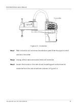
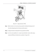
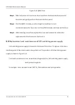
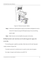
Figure 5-15 QBUS fuse
Step 1
Refer to Section 4.4 to remove the screws from the base interface panel of
the robot and gently pull out the base interface panel.
Step 2
Find the QBUS module, use the straight screwdriver to turn
counterclockwise the fuse cover on the QBUS module, and take out the fuse.
Step 3
After installing a new fuse, tighten the cover and restore the robot after
replacement with reference to Section 4.4.
5.8
Replacement and maintenance of 24V switching power supply
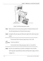
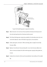
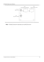
24V switching power supply is located in the base of the robot. To replace it, the base
interface panel of the robot needs to be pulled out. The position of 24V switching power
supply is shown in Figure 5-16.
Tools and accessories: cross screwdriver, diagonal pliers, 24V switching power supply,
static protective gloves.
Screw type: cross recessed screw (M3 * 8), 304 stainless steel spring washer.

