48
Control Elements
6.2.2 Rear View
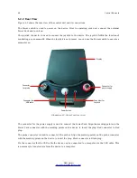
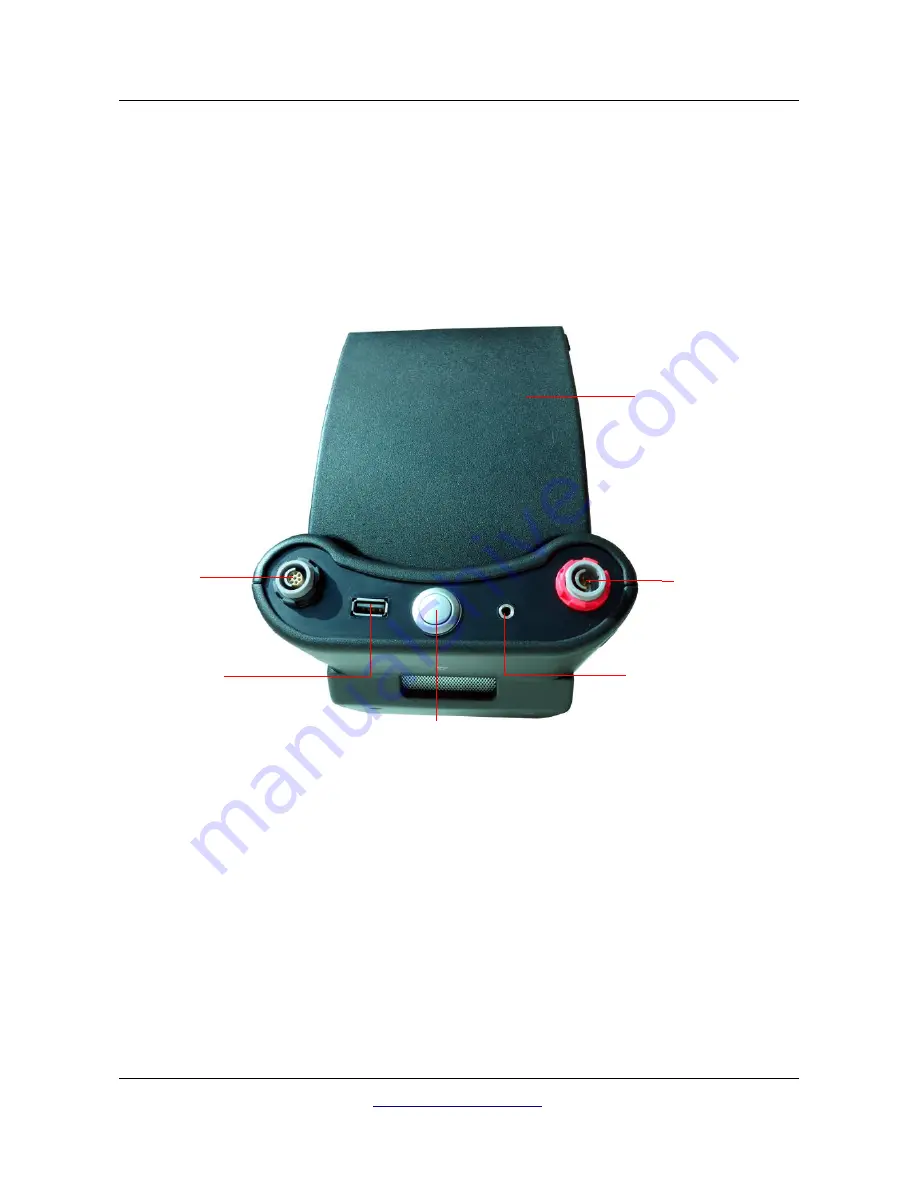
Figure 6.3 shows the rear view of the control unit and its connections.
The Power switch is used to power on the device. Prior to operating your unit, connect the external
Power Pack and turn it on.
The joystick Connector is used to connect the joystick to the device. The joystick fulfills the function of
conducting a scan manually. When the Joystick is not present, you can use the Power switch to execute a
manual scan.
The connector for the power supply is used to connect the Power Pack. Align the marking points on the
Power Pack connector with the marking points on the device to insert the plug. Red connector to Red
plug.
The probe connector is used to connect all the probes. Align the marking points on the probe connector
with the marking points on the device to insert the plug. Black connector to Black plug.
Via the connector for the USB cable the device can be connected to a computer via the USB cable. This
is necessary to transfer data from the device to a computer.
OKM GmbH
www.okmmetaldetectors.com
Illustration 6.3: Control unit, rear view
Connector for
USB cable
Connector for
power supply
Connector
for probe
Display
Power Switch
Connector for
Joystick
Summary of Contents for eXp 4500
Page 1: ...FS Future Series eXp 4500NT Version 1 5 User s Manual ...
Page 5: ...5 9 2 Control Scans 93 OKM GmbH www okmmetaldetectors com ...
Page 9: ...1 Introduction CHAPTER 1 Introduction ...
Page 14: ......
Page 35: ...3 Technical Specifications CHAPTER 3 Technical Specifications ...
Page 39: ...4 Scope of Delivery CHAPTER 4 Scope of Delivery ...
Page 44: ......
Page 78: ......
Page 88: ......


