8
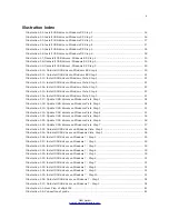
Illustration 7.37: Graph showing thermal values ............................................................................... 74
Illustration 7.38: Thermograph Icon .................................................................................................. 75
Illustration 7.39: Thermograph Display ............................................................................................. 75
Illustration 7.40: Language Icon ........................................................................................................ 76
Abbildung 7.41: Settings Menu .......................................................................................................... 76
Illustration 7.42: Date icon ................................................................................................................ 76
Illustration 7.43: Time Icon ................................................................................................................ 76
Illustration 7.44: Volume Icon ............................................................................................................ 76
Illustration 7.45: Reset to Factory Default Icon ................................................................................. 76
Illustration 7.46: Exit Icon ................................................................................................................. 77
Figure 8.1: Starting position of a scan area ....................................................................................... 81
Figure 8.2: Scan modes to measure an area ...................................................................................... 82
Figure 8.3: Effects of changing the number of impulses and their distance ...................................... 83
Figure 8.4: Comparison of low and high number of impulses ............................................................ 83
Figure 8.5: Different walking speeds during scanning ....................................................................... 84
Illustration 9.1: Position of Super Sensor ........................................................................................... 90
Illustration 9.2: Add additional marks to the Super Sensor aids in the scan. ..................................... 91
Illustration 9.3: Super Sensor Orientation ......................................................................................... 92
Illustration 9.4: Control Scan the same line in both directions. ......................................................... 93
Illustration 9.5: Traditional control scan procedure ........................................................................... 94
OKM GmbH
www.okmmetaldetectors.com
Summary of Contents for eXp 4500
Page 1: ...FS Future Series eXp 4500NT Version 1 5 User s Manual ...
Page 5: ...5 9 2 Control Scans 93 OKM GmbH www okmmetaldetectors com ...
Page 9: ...1 Introduction CHAPTER 1 Introduction ...
Page 14: ......
Page 35: ...3 Technical Specifications CHAPTER 3 Technical Specifications ...
Page 39: ...4 Scope of Delivery CHAPTER 4 Scope of Delivery ...
Page 44: ......
Page 78: ......
Page 88: ......


