18
Control elements
4.1 Control unit
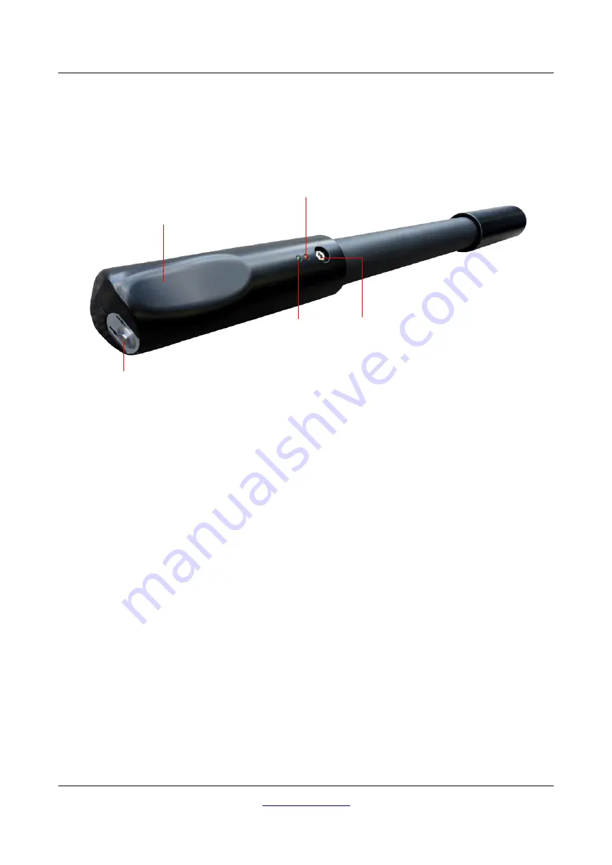
Figure 4.1 represents all control elements of the Fusion Light control unit. The control unit itself is the
scanning probe that can be used in vertical position only.
Battery LED: The battery LED indicates the current charge state of the internal battery during operation. As
long as this LED shines green you have enough power to run your device. When this LED starts blinking you
should recharge the battery.
Socket for Charger / Charge LED: When the green battery LED is blinking during operation you have to
recharge the internal battery by connecting the appropriate charger to the socket for charger. As long as
charging is in progress the charge LED is shining orange. When the charge LED turns off the battery is fully
charged.
Trigger with LED: Push the trigger to power on the detector. The trigger LED shines green now and is ready
to respond to incoming Bluetooth connection requests. As soon as the connection is established, the LED
turns blue. Now you can use the trigger to start scanning, initiate a new scan line (ground scan) or to do a
ground balance (magnetometer). To switch off the unit push the trigger for at least 3 seconds until the LED
turns off.
OKM GmbH
Figure 4.1: Overview of control elements
Socket for Charger
Trigger with LED
Handle
Charge LED
Battery LED
Summary of Contents for Fusion
Page 1: ...Fusion Light User s Manual ...
Page 6: ......
Page 7: ...1 Introduction CHAPTER 1 Introduction ...
Page 12: ......
Page 13: ...2 Technical specifications CHAPTER 2 Technical specifications ...
Page 15: ...3 Scope of delivery CHAPTER 3 Scope of delivery ...


