12
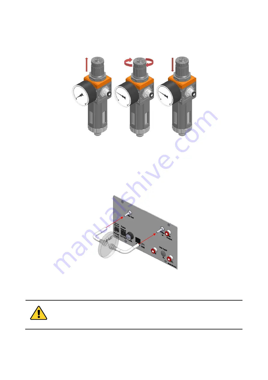
To close the gauge, pull the knob up and rotate it counterclockwise. Push the knob down to lock it. Open
valve on gas supply tank. Adjust Pressure Gauge by pulling the top knob up and rotating it clockwise until the
pressure reaches the desired value (See Figure 8), then push the top knob down to lock it.
A
B
C
Figure 8. Pressure gauge using
2.
Install the
PTFE filter
on the rear panel of the CO2-UNIT-BL. It filters the Air/CO
2
flow coming from their
tanks before entering in contact with sensing cells. It prevents sample contamination from bacteria and gas
sensors from damages caused by dirty gas streams. It is connected with two 4 I.D. mm silicon tubes with the
“Filter In” and “Filter Out” connectors on the r
ear panel of the CO2-UNIT-BL (see Figure 9 and pointer 1 and
2 in Figure 5).
Figure 9. Filter tubing
Tip
►
Replace this filter each 2-3 months of continuous use or when it is present water in the inner part of
the filter.
Do not remove the filters. This may cause damages to the gas sensor and sample contaminations.
3.
Tubing for CO
2
and Air lines are rigid tubing, 6 mm O.D. (TUBE A in par. 4), and they connect to the CO2-
UNIT-BL through Push-in connectors (see Figure 10 and pointer 3 in Figure 1). Make sure to push tubes
securely all the way into connectors avoiding any gas leak. To remove tubing from push-in connectors push


