116
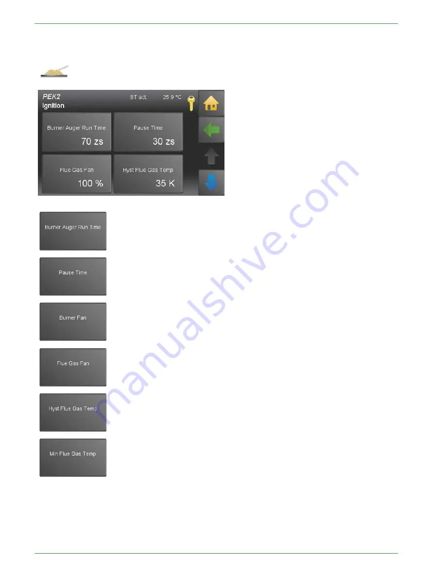
Ignition settings
113
3..114
4..4
4 IIg
gn
niittiio
on
n s
se
ettttiin
ng
gs
s
Run duration of the burner auger during the ignition period,
expressed in tenths seconds.
Rest Time of the burner auger during the ignition period,
expressed in tenths seconds.
Speed of the combustion air fan during the ignition period.
Speed of the flue gas fan during the ignition period.
For a succesful ignition the flue gas temp has to be higher than the
boiler temp
plus
hyst flue gas temp
.
Note:
Display only if flue gas sensor is connected.
Flue gas min temp for the regulation of the boiler performance.
If temperature falls below
Flue gas min temp
, the boiler rises its performance inde-
pendent from the boiler temp.
Note:
Only displayed if flue gas sensor is connected.
On ignition the flue temp is investigated.
Ignition temp =
flue gas temp
plus
Hyseresis flue gas temp
.
If the calculated ignition temperature rises obove the
max flue gas temp
, it is rest-
ricted to this
max flue gas temp
.
Note:
Only displayed if flue gas sensor is connected.
PE 567 EN 1.1
Summary of Contents for PE 08
Page 16: ...16 Wiring diagrams PE 567 EN 1 1 ...
Page 17: ...Wiring diagrams 17 Operating Manual PELLEMATIC PE S K B 10 56 ...
Page 18: ...18 Wiring diagrams PE 567 EN 1 1 ...
Page 76: ...76 Code Input Menu of Pelletronic Touch after entering the code PE 567 EN 1 1 ...
Page 110: ...110 Cascade settings Back to the menu Sys Regulation PE 567 EN 1 1 ...
Page 168: ......
Page 169: ......


