background image

TOTAL POS SOLUTION COMPANY 

OKPOS

Manual

Service

ZED POS

1. Configuration of Main Board

2. Configuration of Major I/O Ports

Appendix

1. Stand

2. Cable Cover

3. Rear Cover

4. Main Press

5. Internal System Configuration

6. Storage Replacement

Assembly / Disassembly

1. System On/Off

2. Touch Screen

3. Disk back-up and Recovery

4. Dual monitor (Optional)

5. Magnetic Stripe Reader (Optional)

System Installation 

and Usage

1. Preview

2. Features and Specifications

3. Parts Description

System Introduction

Make sure the adapter direction before plugging in

CAUTION

3

2

1

A

B

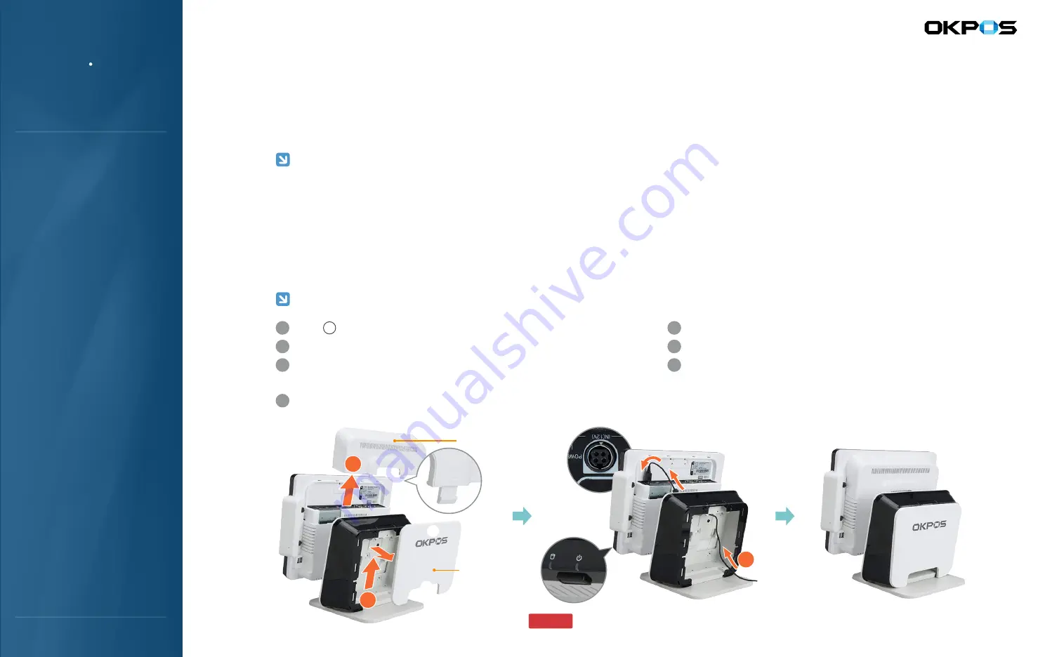
Stand 
Rear Cover

Reassemble the cable cover
Reassemble the stand rear case
Activate the system by pressing the power button

Hold     tightly, and pull up the rear cover for detaching
Push up the cover by press the PUSH parts of cable cover for detaching
Insert the Power adapter cable to power port by following the 
direction of the arrow ③
Connect the peripheral cables to I/O ports on demand

A

7

Cable Cover

6

5

4

3

2

1

System Installation and Turn-on

Install the system where well-ventilated and weight resistive

Keep out of direct sunlight and away from heaters. There is a risk of fire and explosion if it is installed in those areas

Keep away from areas of high moisture and dust because there is a risk of electric shock and electrical short if it is installed in those areas

Definitely connect the power cable to a grounded (earthed) plug

Precautions for Product Installation

●   ●   ●   ●   ●   ●   ●   ●   ●   ●   ●   ●   ●   ●   ●   ●   ●   ●   ●   ●   ●   ●   ●   ●   ●   ●   ●   ●   ●   ●   ●   ●   ●   ●   ●   ●   ●   ●   ●   ●   ●   ●   ●   ●   ●   ●   ●   ●   ●   ●   ●   ●   ●   ●   ●   ●   ●   ●   ●   ●   ●   ●   ●   ●   ●   ●   ●   ●   ●   ●   ●   ●   ●   ●   ●   ●   ●   ●   ●   ●   ●   ●   ●   ●   ●   ●   ●   ●   ●   ●   ●   ●   ●   ●   ●   ●   ●   ●   ●   ●   ●   ●   ●   ●   ●   ●   ●   ●   ●   ●   ●   ●   ●   ●   ●   ●   ●   ●   ●   ●   ●   ●   ●   ●   ●   ●   ●   ●   ●   ●   ●   ●   ●   ●   ●   ●   ●   ●   ●   ●   ●   ●   ●   ●   ●   ●   ●   ●   ●   ●   ●   ●   ●   ●   ●   ●   ●   ●   ●   ●   ●   ●   ●   ●   ●   ●   ●   ●   ●   ●   ●   ●   ●   ●   ●   ●   ●   ●   ●   ●   ●   ●   ●   ●   ●   ●   ●   ●   ●   ●   ●   ●   ●   ●   ●   ●   ●   ●   ●   ●   ●   ●   ●   ●   ●   ●   ●   ●   ●   ●   ●   ●   ●   ●   ●

1. System Installation and Turn-on/off

System Installation

Summary of Contents for ZED5

Page 1: ...Option 9 7 inch Dual DIsplay ZED5 Option 15 inch Dual DIsplay ZED5 Option 9 7 inch Dual DIsplay TOTAL POS SOLUTION COMPANY OKPOS We use the original version of Microsoft windows OS and recommend customers to use them Manual ZED POS Service ...

Page 2: ...re installed no noise low energy consumption Stable System Features 2 Features and Specifications This Class A digital device is developed for use in commercial industrial business environment and is aimed at being used in public places not in homes Class A digital device Product Designs and specifications are subject to change without prior notice Contents of this manual may vary depending on mod...

Page 3: ...Monitor ISO Track 2 Interface USB Equipped for DVR CARD Wall Mount Bracket DSUB 25 Parallel Port Customer Display MSR Raiser Card Wall Mount Printer Port Options INTEL ATOM D2550 1 86GHz Dual Core NM10 DDR3 SODIMM 2GB up to 4GB 2 slots 2 5 inch SATA SSD 64GB 15 inch TFT LCD LVDS 1024x768 15 inch 5 WIRE RESISTIVE TOUCH 4 x RS 232C 3 x DSUB 9P 1 x RJ45 6 4 x I O 2 x SIDE 2 1 x MOUSE 1 x KEYBOARD 1 Y...

Page 4: ...Stripe Reader Optional System Installation and Usage 1 Preview 2 Features and Specifications 3 Parts Description System Introduction PS 2 Keyboard PS 2 Mouse Serial Port DSUB9 COM2 Serial Port DSUB9 COM3 LAN1 Basics LAN2 Reserve Speaker Port DVR Serial Port DSUB9 COM1 VGA Port USB Port Mic Port Serial Port RJ45 COM4 DC OUT Power 12V DC IN Power 12V I O 포트 Cable Holder Stand Rear Cover Cable Cover ...

Page 5: ...stem by pressing the power button Hold tightly and pull up the rear cover for detaching Push up the cover by press the PUSH parts of cable cover for detaching Insert the Power adapter cable to power port by following the direction of the arrow Connect the peripheral cables to I O ports on demand A 7 Cable Cover 6 5 4 3 2 1 System Installation and Turn on Install the system where well ventilated an...

Page 6: ...used in calibration damage to the touch screen may occur This is not the way to be recommended CAUTION After you click the Windows start button select as follows Program PenMount Windows Universal Driver WHQL Utility PenMount Control Panel Select PenMount 6000 RS232 in device selection tab to configure in PenMount Control Panel Press Standard calibration button in the coordinate calibration tab Fo...

Page 7: ...view 2 Features and Specifications 3 Parts Description System Introduction Use it by touching the screen 3 Click Multiple Monitors After checking Multiple Monitors support click Map Touch Screens Touch main screen Press S on the keyboard if use dual Touch touch dual monitor screen Click Configure Click Advanced Calibration Touch as a point target Turn on the system and boot it using OS After doubl...

Page 8: ...ndows Connect the keyboard and mouse to the system After turning on the system follow the 0n screen instructions press the keyboard F11 when the F11 to WinClon message appears on the screen within 3 to 4 seconds PC POST process When Winclon Appears on the screen press F2 key or F3 on your keyboard or click the mouse to select Recover recent state or Recover initial state After entering the passwor...

Page 9: ...d Specifications 3 Parts Description System Introduction Connect the keyboard and mouse to the system After turning on the system follow the 0n screen instructions press the keyboard F11 when the F11 to WinClon message appears on the screen within 3 to 4 seconds PC POST process When Winclon Appears on the screen press F10 on your keyboard or click the mouse to select Back Up After entering the pas...

Page 10: ... Installation and Usage 1 Preview 2 Features and Specifications 3 Parts Description System Introduction Connect the VGA cable and dual power cable Reassemble the cable cover after connecting power adaptor cable 2 1 Connecting Cable 3 2 1 Remove the cable cover Install a dual monitor by sliding it to the direction of arrow Fasten the screw with a coin or driver 3 2 1 Installation This manual is wri...

Page 11: ... 1 Preview 2 Features and Specifications 3 Parts Description System Introduction Connect the VGA cable and dual power cable Reassemble the cable cover after connecting power adaptor cable 2 1 Connecting Cable 3 2 1 Remove the cable cover and stand rear case Detach the stand dual set up part Clear up the edge when it detached Fasten the screw after install the dual monitor on the stand 3 2 1 Instal...

Page 12: ...iption System Introduction 15 inch Dual Monitor Auto Detection Power Button 9 7 inch Dual Monitor Auto Detection Power Button Press the Auto Detection button 6 Extended Mode LVDS extend VGA Clone Mode LVDS clone VGA Turn on power and boot it using OS After click the Windows start button select Setting Control Panel in order and click the Display icon on the Control Panel screen After Display Regis...

Page 13: ... Optional 5 Magnetic Stripe Reader Optional System Installation and Usage 1 Preview 2 Features and Specifications 3 Parts Description System Introduction 1 2 2 Attach the MSR connecter Fasten the screw with a coin or shaped driver 2 2 1 Assemble MSR 2 1 1 Unfasten the screw with a coin or shaped driver Detach the MSR connecter 2 1 Disassemble MSR Please note that the cable can be caught jammed by ...

Page 14: ...2 Features and Specifications 3 Parts Description System Introduction Pull out the cable cover by press the PUSH parts of cable cover for disassembly 2 Cable Cover Disassembly Note when it s put down the floor careful with scratches on the LCD screen and main body Please be careful of dropping the POS system since it s heavy CAUTION 1 3 4 Lift up the fixing lever Unscrew it with a coin or shaped d...

Page 15: ...d Usage 1 Preview 2 Features and Specifications 3 Parts Description System Introduction 1 1 2 3 4 Unfasten two screws which fix the main press Push the main press to the direction of arrow and let it pulled out from the holder Flip over the main press like arrow and disassemble the HDD cable and speaker cable that are connected to the main board 3 2 1 4 Main Press Disassembly 2 1 3 Remove the scre...

Page 16: ...3 Disk back up and Recovery 4 Dual monitor Optional 5 Magnetic Stripe Reader Optional System Installation and Usage 1 Preview 2 Features and Specifications 3 Parts Description System Introduction Main Board Memory LCD Bracket I O Bracket Touch Power Board Touch Cable PCI Slot USB Board Joint Board Power Switching Board Front Panel Board SATA Data Connecter SATA Power Connecter Main parts can be di...

Page 17: ...ew 2 Features and Specifications 3 Parts Description System Introduction 4 2 3 1 Detach the cable cover Unfasten the hand screw following the direction of arrow Hold the hand screw and pull out of the HDD to the direction of arrow Disassemble HDD from the bracket 4 3 2 1 Wear protective gloves when you detach the storage device from the bracket The edge of bracket is very sharp and it may cause hu...

Page 18: ...m On Off 2 Touch Screen 3 Disk back up and Recovery 4 Dual monitor Optional 5 Magnetic Stripe Reader Optional System Installation and Usage 1 Preview 2 Features and Specifications 3 Parts Description System Introduction LVDS Connector LCD Backlight Connector Radiator Heat sink Mainboard Power Connector Memory Slot 2 Memory Slot 1 Battery PCI Slot SATA Data Connecter Parallel Connecter Buzzer CMOS ...

Page 19: ...s Description System Introduction Pin Num 1 2 3 4 5 6 7 8 Description GND DSR TXD RXD RTS CTS GND DTR COM4 RJ45 8 1 Pin Num 1 2 3 4 5 6 7 8 9 Description DCD RXD TXD DTR GND DSR RTS CTS COM Voltage RS 232 communication COM1 2 3 6 1 Serial Ports COM1 2 3 RJ45 Pin Num 1 2 3 4 5 6 Signal KBDAT NC GND KB5V KBCLK NC Keyboard Data No Connect Ground 5VSB Power Sourcd Keyboard Clock No Connect Mouse Data ...

Page 20: ...cription System Introduction Pin Num 1 2 3 4 Description 12V GND 12V GND Adapter Input 12V 3 1 4 2 Power Output port Pin Num 1 2 Description 12V GND Secondary Display Output 12V 2 1 Power Output port Pin Num 1 2 3 4 Description Transmit Transmit Receive Reserved Pin Num 5 6 7 8 Description Reserved Receive Reserved Reserved LAN port RJ45 8 1 Pin Num 1 2 3 4 Description VUSB 5V D D GND USB port TYP...

Page 21: ...Rev ZED_1 00A_1503_ENG Ver Main number 1566 9051 Customer service center 1566 9059 Tell 801 802 ACE High End Tower 6th 234 Beotkkot Ro Geumchun Gu Seoul 153 801 Address ...

Reviews: