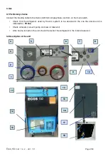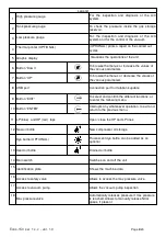
Legend
1
High pressure gauge
For the inspection and diagnosis of the A/C
system
2
Tank pressure gauge
To check the pressure inside the gas storage
reservoir.
3
Low pressure gauge
For the inspection and diagnosis of the A/C
system and for the control of the vacuum.
4
Thermal printer (OPTIONAL)
(OPTIONAL) prints a report on the carried out
cycles
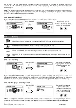
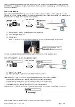
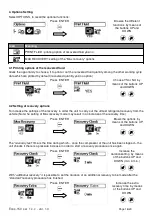
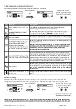
5 Graphic display
Visualizes the operations of the unit
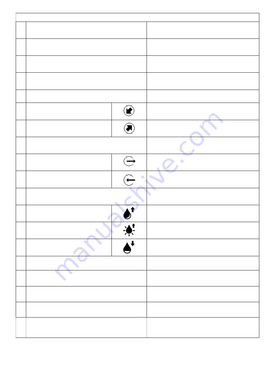
6 Button “Down”
To browse the menus or increase the values of
the various parameters
7 Button “UP”
To browse the menus or decrease the values of
the various parameters
8 USB port
Connection port for databank update
9 Button “EXIT”
To select and confirm the different functions, or
to enter the following menu
10 Button “ENTER”
Interrupts any whatsoever operation, to exit and
return to the previous menu
11 LP (blue) and HP (red) taps
Open /close the HP and LP lines
12 New oil bottle
New compressor oil storage
Dye bottle (OPTIONAL)
Fluorescent dye bottle can be added as an
optional
13 Used oil bottle
Drained oil bottle
14 Main switch
Switches on and off the unit
15
Identification plate
Shows the machine data
16
Access to safety valve
Allows to access the max pressure valve
17
Access to vacuum pump
Allows the vacuum pump inspection
18
Max pressure valve
Automatically releases pressure if max pressure
is reached. Allows to manually release NCG
gases, if present
Ecos-150 sw 1.x.x - ver. 1.0
Page 8/20


