background image

EMA Thickness gauge EM4000.   User Manual


+7(812) 385-54-28 

info@oktanta-ndt.ru 


15


Date


This menu allows you to set the date in the device. 


Time


This menu allows you to set the time in the device. 


Language


The  device  allows  you  to  choose  one  of  three  interface  languages: 
Russian, Chinese and English. 


Units


This parameter can take the value of millimetres or inches. 

Files window


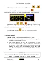
The appearance of this window is shown in the figure below: 


Files window


To enter this window, press the 

 button. After that, the appearance of the 

window will change and become as shown in the figure below: 


Summary of Contents for EM4000

Page 1: ...EM4000_M_921806721 7 812 385 54 28 info oktanta ndt ru Electromagnetic acoustic thickness gauge EM4000 User Manual Saint Petersburg 2021...

Page 2: ...an window 10 Settings window 13 Files window 15 Presets and calibration 16 Measurement of the thickness of the test sample 23 Measurement of coating thickness at the test sample 25 Data saving 26 Batt...

Page 3: ...The ultrasonic method is used to measure the thickness of a metal sample The eddy current method is used to measure the thickness of non conductive coatings The ultrasonic method for measuring thickn...

Page 4: ...measurement error 0 1 mm 3 Permissible misalignment of the sensor relative to the normal to the surface of the test sample 25 The minimum permissible radius of curvature of the surface of the test sam...

Page 5: ...new one due to the presence of a quick detachable connection Control buttons have the following functions OK button turning on off the device as well as the navigation button in the device menu Retur...

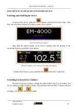
Page 6: ...screen Device information window After that the main window of the device appears with the display of the measured thickness and other information The main window of the device with information displa...

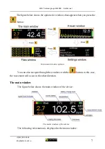
Page 7: ...pear when you press the button Instrument window options You can also navigate through the windows with the button in this case the movement will occur in the other direction The main window The figur...

Page 8: ...s field displays the measured thickness value of the non conductive coating at the test sample Thickness This field displays the measured value of the thickness of the test sample Averages This field...

Page 9: ...t press the button to enter the edit mode for the value of this field In this case the highlight colour of the selected field will change to a darker one as shown in the figure below In the mode of va...

Page 10: ...ee the Settings window section In addition to the A scan this window also displays the measured thickness of the test sample The gain level in the device is shown in the right part of the window The u...

Page 11: ...the user can navigate the A scan by pressing the or buttons To exit the scale mode press the button Pressing the button again leads to reset of all changes of the A scan scale and setting the scale t...

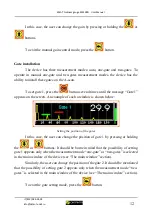
Page 12: ...ate 1 appears on the screen An example of such a window is shown below Setting the position of the gates In this case the user can change the position of gate 1 by pressing or holding the or buttons I...

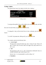
Page 13: ...alues of the selected line or enter a submenu press the button To exit the line parameters editing mode use the button This window contains the following lines A scan length This parameter can take th...

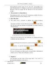
Page 14: ...ss measurement channel To enter this menu press the button In this case the user enters the submenu the appearance of which is shown in the figure below Coating thickness measurement channel calibrati...

Page 15: ...ice Language The device allows you to choose one of three interface languages Russian Chinese and English Units This parameter can take the value of millimetres or inches Files window The appearance o...

Page 16: ...e required number of times Presets and calibration There are a number of steps to take before starting measurements 1 In the main window of the device select the material of the test sample from the l...

Page 17: ...of 20 80 C ATTENTION Using the EMT40001 converter at temperatures above 80 C may damage it EMT40004T converter characteristics Excited wave type Transverse radially polarised Working frequency range...

Page 18: ...lect a material the speed of sound is automatically set from the default values for that material But the user can set any value of the speed of sound if it is known more precisely The device uses a t...

Page 19: ...ate thickness measurement algorithm The automatic algorithm is suitable for most applications and allows you to obtain the thickness value without operator intervention The algorithm for measuring the...

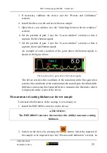
Page 20: ...ppearance of such a window is shown below Highlighted thickness value Next you need to press the button and using and buttons set the real known value of the sample thickness instead of the measured v...

Page 21: ...priate menu item and press the button After that the text Place the device outside metal objects and press OK appears on the screen of the device The device should be removed from the metal so that th...

Page 22: ...ence coating The very value of this thickness is indicated on the sample supplied Install the instrument on the sample as shown in the figure below Positioning the device for zero calibration and pres...

Page 23: ...ice see the Presets and Calibration section 4 Place the device on the surface of the test sample After a period of time from 100 ms to 3 seconds depending on the selected number of averages the measur...

Page 24: ...als as shown in the figure below Gate location over multiple bottom signals In both cases the device searches a maximum on the A scan within one gate and it is this maximum that is taken as the one by...

Page 25: ...bottom signals is shown in the figure below The location of two gates above the bottom signals The device searches the coordinate of the maximum in the first gate then searches the coordinate of the...

Page 26: ...nnel has an edge effect This means that if the device is placed close to the edge then the readings of the measured coating thickness will not be correct Therefore do not position the device so that t...

Page 27: ...ing the converter near knives forks needles or other sharp metal objects Such objects can become magnetically attached to the convert housing and injure the operator 2 When installing the converter on...

Page 28: ...documentation a mark on verification is put on the device or a verification certificate is issued In case of negative results of verification the device is not allowed for further operation in the te...

Page 29: ...on must be carried out under the following climatic conditions Air temperature 5 30 C Humidity 80 at a temperature 25 C Atmosphere pressure 86 106 kPa Verification procedure Visual inspection When con...

Page 30: ...than 0 04 mm Determination of measurement error Determination of the measurement error is performed using a set of samples made from one workpiece in the following order 1 Place the device on a 2 mm...

Page 31: ...them with new ones ATTENTION It is recommended to replace the converter when the device is turned off To replace the EMT40001 converter it must be disconnected from the device For this 1 It is necessa...

Page 32: ...n The replacement of the EMT40004T converter is carried out in the same way but the calibration of the coating thickness measurement channel should not be done since the EMT40004T converter does not h...

Page 33: ...tore and transport the device only in the case included in the delivery kit In this case it is necessary to avoid mechanical damage to the case and the device When stored for a long time the battery o...

Page 34: ...34 DELIVERY KIT Basic kit EM4000 thickness gauge 1 pc Device storage case 1 pc Charger 1 pc EMT40001 converter 1 pc USB C cable 1 pc User manual 1 pc CP40001 SOP 1 pc Optional equipment EMT40004T conv...

Page 35: ...obligations in the following cases 1 Use of the device for purposes other than those specified in this user manual 2 Violation of the conditions and requirements for operation storage and transportat...

Page 36: ...EMA Thickness gauge EM4000 User Manual 7 812 385 54 28 info oktanta ndt ru 36 REPAIR INFORMATION Date of the request Type of the defect Repairs carried out Completion mark date signature seal...

Page 37: ...EMA Thickness gauge EM4000 User Manual 7 812 385 54 28 info oktanta ndt ru 37 VERIFICATION INFORMATION Verification date Validity Implementer data...

Reviews: