


Page 6
www.oldschoolmodels.com
Construction Manual
Step 26 - Wing Assembly (attach sheeting)
Take two of the completed
leading edge sheets from the
previous step as they will be
glued in position on the top of
the wing, as shown here.
We find it best to lay a bead
of glue along the edge of the
sheeting where it butts up
against the leading edge .
Make sure it is also contacting
each of the ribs. As a general rule, don’t use super-fast curing C/A’s
for the step as you will need a bit of time to make sure everything
is in place.
Glue one sheet on the left and the right wings.
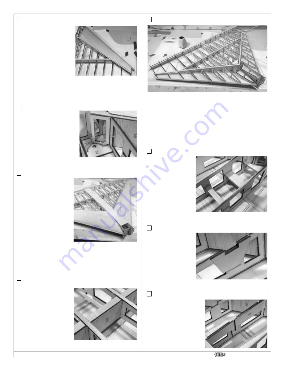
Step 27 - Center Section (install F4)
Locate both F4s from the LP2
sheets. These are glued in place
as shown here, adding structural
strength by tying both the upper
and lower front spars to the
center section.
Don’t go overboard, but do use
a good amount of glue to make
sure these pieces are properly
secured to the spars and to the center section sidewalls (R1).
Step 28 - Center Section (top sheeting)
Using a bit of the leftover
1/16” sheeting from the BP6
and BP8 sheets, measure,
cut and glue together the
sheeting to cover the top of
the center section.
When measuring, make sure
that the grain is crosswise
(flowing from R1 to R1).
When edge gluing the
sheeting pieces together, first
make sure the edges are flat
(give a quick, swipe or two
with a sanding block).
Work from the rear of the center section, forward. You’ll need to
cut and join a few pieces together but be sure to stop an inch or
two behind the F5 (nose gear mount). You’ll need this open to aid
in mounting your powerplant.
Step 29 - Wing Assembly (cap strips)
Cut several 1/16th x 1/4” x
36” balsa strips from BP9.
Carefully measure and cut cap
strips to cover the top of each
R2-R8 rib. These strips should
be centered on each rib and
extend from the trailing edge
stock up to the back of the
leading edge sheeting.
Step 30 - Wing Assembly (tab removal)
Once all the glue has cured, remove the Comet assembly from the
building surface and flip it over.
Now it’s time to remove all the tabs from the ribs. All ribs will have
a rear and forward tab, as well as the smaller tabs that held the
lower spars in place. All of them need to be carefully cut away
and the ribs lightly sanded to maintain their airfoil shapes. There’s
a number of ways to do this but we find a Japanese saw is the
perfect tool. These saws are small, have flexible blades and the
lack of off-set teeth makes a smooth, straight cut.
Step 31 - Center Section (servo rails)
You should have several
leftover lengths of the
3/16” x 3/8” basswood
from trimming the spars.
These pieces will be used
to create the servo rails in
the center section. You’ll
need two of them - one
rear, one front, and two
which are back-to-back in
the middle slot.
Glue these in position.
Step 32 - Wing Assembly (R3C)
Locate both R3Cs from
LP2. These are doublers
for the main gear. They
are attached to the inside
edge of each R3. The
groove should line up
with the matching groove
in R3, and the edges of
R3C and R3 should be
flush with each other.
Step 33 - Wing Assembly (R2C)
Locate both R2Cs from LP1.
These are also doublers for the
main gear. They are attached
to the inside edge of each
R2. The long slot should be
aligned in the middle of the
slot in R2. Also, the edges of
R2C and R2 should be flush
with each other.


