Construction Manual
www.oldschoolmodels.com
Page 23
Installing the fl aps:
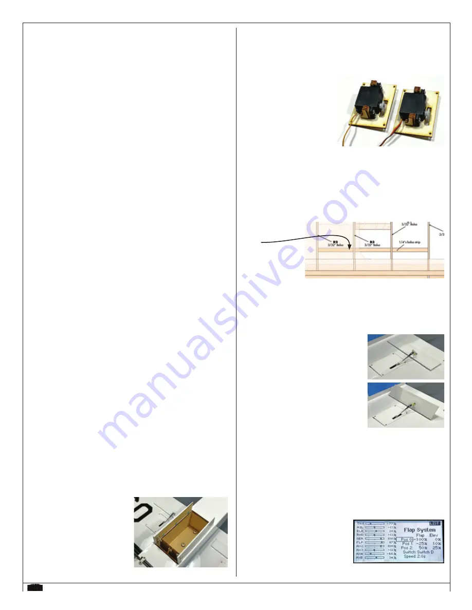
Locate the other two SH1s from LP7, as well as twelve of the "
L
"
shaped pieces and 4 of the small rectangles from LP8.
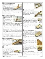
Using the same techniques you used when creating aileron servo
rails, you'll make 4 servo rails, then glue the rectangle on top.
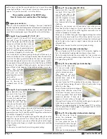
This time however you
won't make two mirror
images - these both need
to match, as shown here in
the pic
.
Center the servo arm as
before, then glue the rails on
each side of the servo.
These fi nished hatches can then be covered, and mounted into the wing.
Note: you may have to remove the covering in the fl ap servo bays, if you
haven't already. And the servo wires are run through the ribs and exit out
the same center holes the aileron wires are exiting. These servos should be
connected to a "Y" harness, then into a spare channel of your receiver -
hopefully one that works via a 3-position switch on your transmitter.
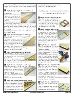
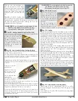
In the wing, there was a single 1/4" x 1/4" piece that was installed between
ribs R2 and R5, on
the underside of the
wing.
This is the piece that
the fl ap's hinges will
be mounted to.
Using the same
hinging technique as before, mark the three places where you'll need to cut
slots to match the hinges already glued to the fl aps. Then insert one of the
fl aps and make sure the hinges are all the way into the wing. Use drops of
thin C/A glue to attach the fl ap.
Then do the same to mount the remaining fl ap under the other side of the
wing.
Now you'll connect the control horns and the
back to the FP4 plate, using two of the 2-56 x
5/16" screws for each fl ap.
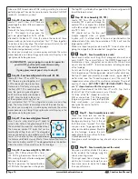
Short pushrods are then hooked up between
the servos and control horns. When the servo
is at one extreme, both fl aps should be fl at
against the bottom of the wing. When the
servo is extended, the fl ap should be at
roughly a 45° angle, as shown here.
Flaps are meant to be used at slower speeds
to increase the lift dramatically - and allowing
for higher rates of climb and much slower fl ight.
DON'T DEPLOY THESE AT
SPEEDS OVER 1/2 THROTTLE, as you could damage them.
Also, when deploying them, the GHOST will tend to climb, and sometimes
climb signifi cantly, so you'd need to hold more down-elevator to keep it
fl ying level. This is not unique to the GHOST - it's the way fl aps effect most
designs - but if your radio allows, you can add some mixing to automatically
add down elevator when the fl aps are deployed.
We found it best to use fl aps on channel with a 3 position switch. When
retracted completely, no need for
elevator trim. When the fl aps were half-
way extended, we mixed in 10% down
elevator. With full fl aps, we mixed in
25% down elevator. You're mileage may
vary, but these are good starting points.
cases, the radio should be charged the night before going out fl ying.
Check the radio installation and make sure all the control surfaces
are moving correctly (i.e. the correct direction and with the
recommended throws). Test run the engine and make sure it
transitions smoothly from idle to full throttle and back. Also ensure
the engine is tuned according to the manufacturer’s instructions, and
it will run consistently and constantly at full throttle when adjusted.
Check all the control horns, servo horns and clevises to make sure
they are secure and in good condition. Replace any items that would
be considered questionable. Failure of any of these components in
fl ight would mean the loss of your aircraft.
Range check your radio before fl ying
Before each fl ying session, range check your radio. This is
accomplished by turning on your transmitter with the antenna
collapsed. Turn on the radio in your airplane, but do not attach the
arming switch.
With your airplane on the ground, you should be able to walk 30
paces away from your airplane and still have complete control of all
functions.
If not, don’t attempt to fl y! Have your radio equipment checked out
by the manufacturer.
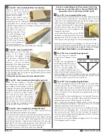
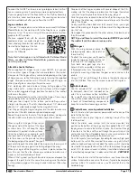
Shot of our DX18 transmitter's
fl ap setup for the GHOST.
Installing the Fun Fly Bay Accessory kits
(available separately)
:
As you probably know by now, we are developing several accessory
kits that can be mounted inside the GHOST's fuselage. Each of
these will mount the same way.
With the wing removed, you can look down on the two CG8/9 rails
that were installed during the fuselage build. There are two holes
pre-cut into them. Run a 3/32" bit through these holes to make
sure they're free of glue.
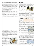
Now with that fi nished, each of the accessory kits will push in
from the bottom and mount using the two supplied 4-40 x 1"
socket head cap screws from the
hardware bag, as shown here.
Simply bolt in the module with
the screws (through the wing
saddle after the wing is removed),
then plug the servo into a spare
channel that you'll use to control
the module. Do the reverse to
swap out to another module.


