background image

         Construction Manual 

www.oldschoolmodels.com 

Page 7

■ 

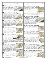
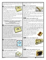
Alignment triangle

Before we start on the wing construction, 

there's a couple of tools that are pre-cut 

into this kit.

One is a 90° triangle in LP1. It can be 

used to vertically align any of the parts in 

the construction of your GHOST. LP1 also 

includes a foot piece that can be used with 

the triangle to hold it vertically (hands-free).

■ 

Step 24 - Wing Assembly (prepare your work area)

Position the port wing plan over your 

fl at building surface and tape it in 

position. Tear off a length of waxed 

paper long enough to cover that 

portion of the plan and tape that over 

the plan. 

■  ■ 

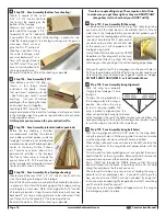
Step 25 - Wing Assembly (bottom spar)

Locate one of the 3/16" x 3/8" x 36" 

basswood sticks. This is used as the 

lower wing spar. Position it on the plans 

so it extends roughly a 1/4" past the tip, 

as shown here. Now move to the other 

end and mark the stick about 1/4" past 

the innermost (root) rib - R1.

Cut this stick to length.

Then it needs to be attached in place over the plans. We use a few 

drops of medium C/A to tack-glue this piece to the waxed paper 

to hold it in place, instead of t-pins. Use your long straight-edge 

to make sure it is aligned properly and is straight over it’s entire 

length. The alignment of this spar is critical as the rest of the wing 

panel is based off this single piece.

■  ■ 

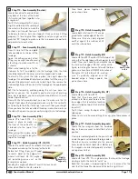
Step 26 - Wing Assembly (LE1, LE2)

Locate one LE1 and one LE2 

from BP11. These two pieces 

will become the lower portion 

of the leading edge.

Pin LE1 in place fi rst, then 

apply glue where LE2 and LE1 

contact each other - around that  

modifi ed "scarf" joint.

Pin LE2 in place, using your 

straightedge to guarantee the straightest of straightnessship.

■  ■ 

Step 27 - Wing Assembly (TE1, TE2)

Locate one TE1 from BP11 and  TE2 

from BP15. These two pieces will 

become the lower portion of the 

trailing edge.

Pin TE1 in place fi rst, then apply glue 

where TE2 and TE1 contact each 

other - around that  modifi ed "scarf" 

joint.

Pin TE2 in place, using your 

straightedge to again guarantee the most straightest of straightness 

that has ever been straight.

■  ■ 

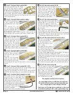
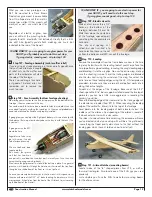
Step 28 - Wing Assembly (T1, T2, T3, T4)

Locate T1 from BP10 as well as T2, T3 

and T4 from LP4.

Place T1 fl at on your building surface, 

in the same orientation as shown on the 

plans, then you'll glue T2, T3 and T4 into 

T1. Make sure each piece is perfectly 

vertical - remember that 90° triangle?

■  ■ 

Step 29 - Wing Assembly (R7)

Locate one R7 from BP6. It is 

glued to the tip assembly you just 

made. Test fi t it fi rst, making sure 

you know how all the tabs in each 

of the T1-4 pieces fi t.

When you're ready, remove R7, 

apply glue in the correct spots 

and attach R7 in place.

■  ■ 

Step 30 - Wing Assembly (tip assembly)

The tip assembly is now glued in 

place to the spar, as well as the 

leading and trailing edges. You'll 

note that there are notches in the 

leading and trailing edges which 

help position this rib, as well as the 

rest of them (as you'll fi nd out).

This tip assembly will also rest on 

the spar, holding it 90° without the use of tools - yup, another great 

innovation from the OSMW Design Squadron Think-Tank.

Anyway, once you see how it's attached, apply glue to the spots 

where the tip assembly contacts the other parts, then glue it in 

place.

■  ■ 

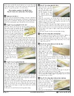
Step 31 - Wing Assembly (webs)

Enter the webs, W3 shear-webs that is.

You'll have a bunch of these on BP11, 

BP14 and BP15. You'll use one of these 

along with a rib over the next few steps.

These webs add massive strength to a 

wing, with very little weight.

These webs do fi ve things at the same time. 

1.  They give you proper rib spacing with tabs that lock into the 

rib's pre-cut slots (our exclusive WEB-LOCK construction).

2.  They hold each rib perfectly vertical without needing tools.

3. The cutout GHOST face lets you easily know which way is 

up - an upright face is the correct way. 

4. The eye cutouts allow airfl ow between the different 

chambers of the wing.  This is very helpful in keeping 

covering from bubbling up when you're covering later on, 

and when the GHOST is at the fi eld in the boiling sun. 

5. 

They just look really cool.

Yup, another bright idea from the warped minds of those who work 

at the OSMW Development Center.

■  ■ 

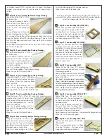
Step 32 - Wing Assembly (W3, R5)

Locate one R5 from BP4, BP5 or BP6. Also locate one W3 web and 

test fi t it against R7. It should be placed so the face is upright, it's 

tab is pushed fully into the slot in R7, and this web is fl ush against 

Summary of Contents for GHOST

Page 1: ...atteries wheels etc throughout the building process You must correctly install all R C and other components so that the model operates correctly on the ground and in the air Installation shown in the...

Page 2: ...r cut 1 8 x 4 x 12 balsa 1 BP2 laser cut 1 8 x 4 x 12 balsa 2 BP3 laser cut 3 32 x 4 x 12 balsa 2 BP4 laser cut 3 32 x 4 x 12 balsa 2 BP5 laser cut 3 32 x 4 x 12 balsa 2 BP6 laser cut 3 32 x 4 x 12 ba...

Page 3: ...s this means that the step will be done twice once for each wing half There could be a step or two which leaves you a bit puzzled If this happens step back and study the photo s for that step both in...

Page 4: ...tween the ailerons and fuselage Flaps create more lift at slower flying speeds and also to slow the plane on landing approach FUSELAGE the main body of an airplane excluding wings tail and everything...

Page 5: ...position until the glue cures Step 6 Vertical Fin Assembly VF8 Locate one VF8 from BP17 Apply glue to the rest of the exposed fin framing and to the edge of VF7 that will touch VF8 Place VF8 on top of...

Page 6: ...led Once finished set the completed stab aside Step 20 Elevator Assembly E1 E2 Locate both E1s from BP2 and two E2s from BP17 Position the E1s so they are mirror images of each other Then working with...

Page 7: ...ight Step 28 Wing Assembly T1 T2 T3 T4 Locate T1 from BP10 as well as T2 T3 and T4 from LP4 Place T1 flat on your building surface in the same orientation as shown on the plans then you ll glue T2 T3...

Page 8: ...will make perfect sense later on in the build Step 38 Wing Assembly R5 W3 Locate two R5s from BP4 and BP5 and two more W3s Still working your way inward these webs and ribs are glued in place one at a...

Page 9: ...t the root R1 rib Now using your trusty straight edge you need to cut two pieces One will be 3 x 36 and the other will be 3 4 x 36 Step 51 Wing Assembly leading edge sheeting Set the 3 4 width piece a...

Page 10: ...at many of the parts will need to be glued to the opposite side the shear webs for instance Always refer to the plans to make sure you re gluing the parts together in the correct way Step 59 Wing Asse...

Page 11: ...s you ve made or eaten in your life this one needs to be perfectly aligned with no condiments running into the pre cut holes And by condiments I mean glue Step 63 Wing Assembly WH2 WH3 Locate WH3 from...

Page 12: ...ll Make sure all the joints are nice and flat along their entire length while the glue cures Again a weight tape and or pins could be of benefit here Do the same to make the other matching side sheeti...

Page 13: ...ge framing Using the scrap 3 16 x 3 16 x 36 balsa stick measure and cut two pieces that go from the front of the landing gear blocks forward to the notch in the plywood sides as shown here Glue this i...

Page 14: ...holes are aligned between the two parts The F4Cs go across the top and bottom of F4A Note their positions in the photo The top F4C is just below the upper tabs The lower is aligned with top of the lo...

Page 15: ...g slots pre cut into both sides of the fuselage Step 93 Fuse Assembly servo rails Now go back to step 89 and repeat everything you just did so now you can mount the servo into the other fuselage side...

Page 16: ...g steps These require a bit of time to make sure you get them right as they can DRASTICALLY change how well or how bad your GHOST will fly Step 107 Fuse Assembly fit the wing It s been awhile but reme...

Page 17: ...he fuselage When gluing this in place make sure that it is straight along the top of the fuselage Step 113 Hatch Assembly H1 H2 H3 Locate H1 and H2 from LP4 and both H3s from LP1 and LP2 These pieces...

Page 18: ...ll rectangle on top of each rail as we ve shown here Step 124 Fuselage Assembly throttle servo mount Now you can drill and attach the servo to the mount using the servo s mounting screws Do a little p...

Page 19: ...ike to mount in this space cover this area with more of the 3 32 x 4 balsa sheeting And make sure it s still cross grained It should run from the front of the LG block to just covering up the bottom o...

Page 20: ...re still 1 long but roughly a 1 4 wide You ll need 6 lengths total Step 139 Flaps hinges Now flip each of the flaps over so the FL4 is facing down and the leading edge is facing you similar to this ph...

Page 21: ...hould and doesn t bind When all that is good you ll push the aileron down and expose the hinges at the joint but at the same time making sure the aileron is still pushed up against the wing it didn t...

Page 22: ...obably want to dial these down a bit to give a smoother appearance to your maneuvers Aileron 1 2 up down 25 expo Elevator 1 4 up down 20 expo Rudder 3 4 left right 15 expo Expert tip Once the control...

Page 23: ...effect most designs but if your radio allows you can add some mixing to automatically add down elevator when the flaps are deployed We found it best to use flaps on channel with a 3 position switch Wh...

Page 24: ...Page 24 www oldschoolmodels com Construction Manual www oldschoolmodels com Construction Manual APPENDIX A...

Page 25: ...Construction Manual www oldschoolmodels com Page 25 Construction Manual www oldschoolmodels com Page 25 APPENDIX A...

Page 26: ...oduct proven to be defective The user shall determine the suitability of the product for his or her intended use and shall assume all risk and liability in connection therewith If the buyer is not pre...

Reviews: