Page 10
www.oldschoolmodels.com
Construction Manual
Step 68 - Fuselage Assembly (Create WS6 assemblies)
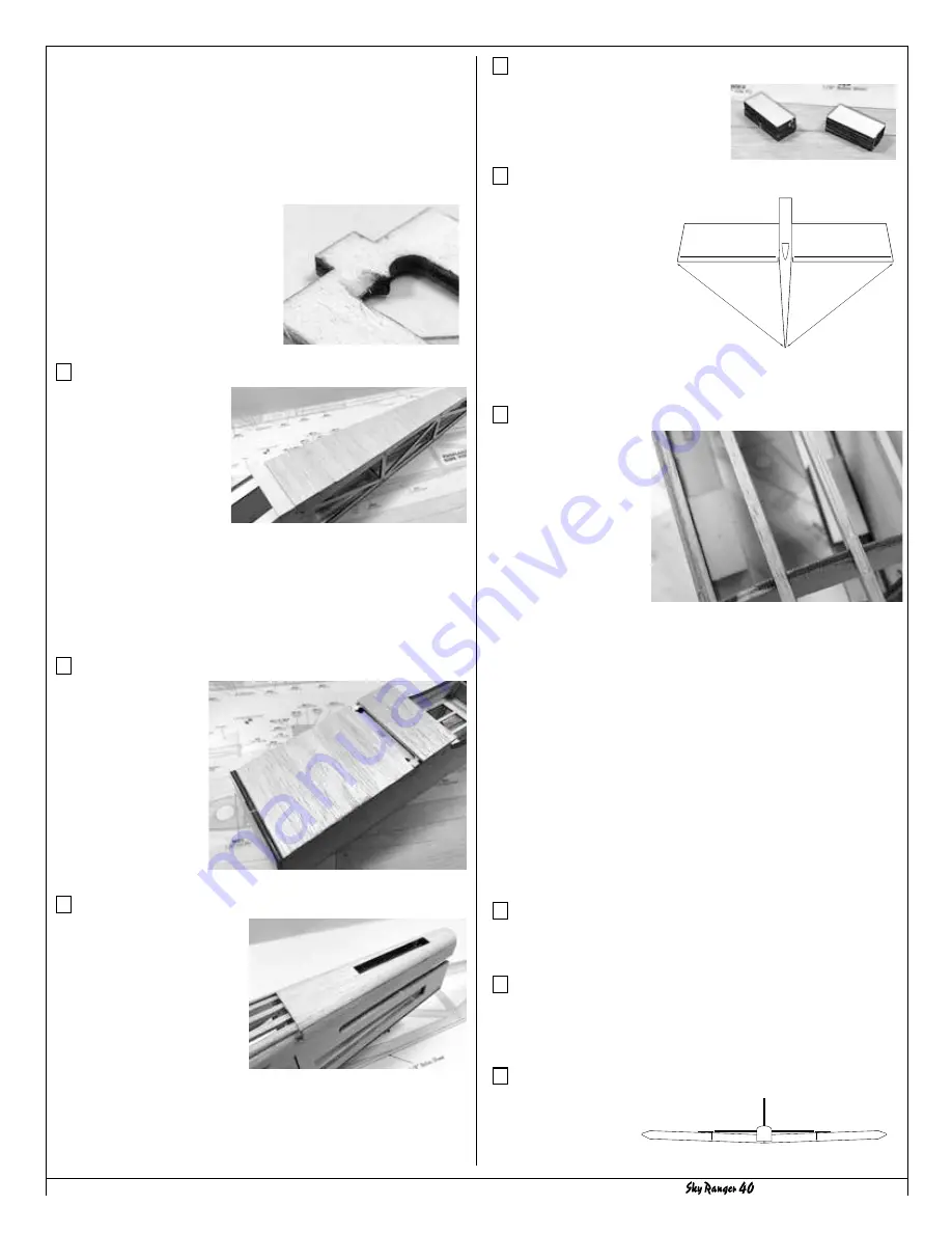
Locate the ten WS6s from both LP2s.
You will make two blocks using these
WS6s, gluing them in two stacks of
five pieces. Put these aside for now.
Step 69 - Fuselage Assembly (Wing alignment)
To align the wing properly
on the fuselage, place the
wing in position, by pushing
in the dowels first, then
allow the wing to rest in
the wing saddle. The wing
is perfectly aligned when the
distance from the left wing tip to
the rear of the fuselage is the same
the distance when measured from
the right wing tip.
Step 70 - Fuselage Assembly (Install WS2 assemblies)
With the wing aligned,
drill two 3/16” holes for
the wing bolts. Using the
precut holes in the WH6/
WH7 assemblies as a
guide (already installed
in the wing), carefully
drill down through
the WH8/WH9/WH10
assemblies on each side
of the fuselage.
Use caution to make sure the wing does not move until both holes
are drilled.
When drilling, take your time and make sure the drill is held so the
bit is perpendicular with the wing’s sheeting. This will make it so
the wing bolt goes in at an angle, but the screw’s head will be flat
on the wing surface.
Drill through the wing and into the fuselage’s WS3.
Remove the drill, remove the wing and clean up WS3 around the
new hole you drilled.
Now locate the WS6 blocks from the previous step and glue them
in position on top of the WS3s, centering them on the holes you
just drilled - as shown here.
Run a 1/4x20 tap through the WS6 pieces so that the wing bolts
will thread into the WS6 blocks.
Step 71 - Fuselage Assembly (Enlarge bolt holes in wing)
Enlarge the wing bolts hole from 3/16” to 17/64”, allowing the
wing bolt to pass through easily. Then mount the wing.
Step 72 - Fuselage Assembly (Round stab/fin leading edges)
Before installing the vertical fin and stab into the fuselage, take the
time to sand them and round off the leading edges of both pieces.
It’s much easier to do this now than to try it after they’re installed.
Step 73 - Fuselage Assembly (Stab alignment)
Although we’ve done
everything possible
to engineer the Sky
Ranger 40 so it will
form a sturdy block for the landing gear wire.
Slide one of the LG2 pieces into the pre-cut slots on the fuselage
sides. Now, paying close attention to the orientation of LG2 holes,
begin sliding the remaining LG2 pieces in place - one at a time
and gluing them in position. Make sure to keep any glue out of
the holes. As these pieces are laminated together, they will align
themselves in the slot.
After the last LG2 is installed, the LG1 is glued in place.
Now run a bit of extra glue around
the LG2 pieces where they meet up
against the fuselage sides.
The last part of this step involves
filing a bit of the cutout in LG1. This
is done in two spots, in the slots
opposite of the holes to give relief
for the landing gear wire.
Step 65 - Fuselage Assembly (F11 & Sheeting)
Locate F11 from LP4 and
install it on the bottom of
the fuselage, just aft of the
wing saddle.
Now, first using the leftover
1/8” sheeting from LP3,
then using the included
1/8” x 3” sheet, it’s time to
sheet the bottom of the fuselage.
This is done a piece at a time, starting at the back (up against
TW1). Hold the 1/8” sheeting against the fuselage, making sure
the grain is cross-ways. Mark, cut and glue a portion of the sheeting
in position. Using this same technique, work your way forward until
you reach F11.
Step 66 - Fuselage Assembly (Forward sheeting)
Using the same
sheeting technique,
and the same 1/8”
sheeting, sheet the
bottom of the front of
the fuselage.
Sheeting should butt
up against the back
of F2 and make sure
not to sheet over the
openings in LG1.
Step 67 - Fuselage Assembly (Fuselage sanding)
Now it’s time to give the
fuselage a good sanding.
Sand the bottom sheeting
so it’s flush with the fuselage
sides. Sand F1 and F2 so they
are also flush with the fuselage
sides, and with the bottom
sheeting. Sand away any extra
sheeting that extends into the
wing saddle. Also take the time to round off F10 so it matches the
slope and curvature of the stringers.
A
A
B
B


