94MS20 Rev. B4
9-13
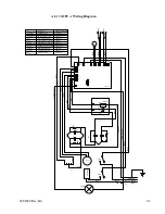
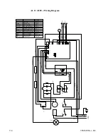
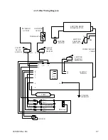
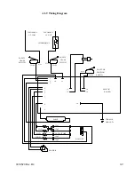
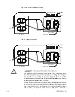
voltage between the lamp lead common and the high blue (about 150V~,
see diagram).
Should one or more of these voltages be about 270V~, the respective
capacitor is not being pulled into the circuit and the P.C. Board is most
likely at fault. Should the voltage be unchanged from the previous power
level, a bad capacitor or bad connection between the capacitor and the
P.C. Board is most likely at fault.
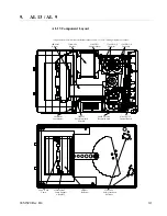
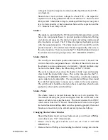
Shutter
The shutter is controlled by the P.C. Board with information from a switch
below the component chassis to provide position information. During
cool-down and exposure, the shutter is open and during warm-up and
idle, the shutter is closed. The P.C. Board compares the shutter position
with the requested position. The shutter motor will run until the switch
position matches. The shutter motor brakes magnetically when it is in
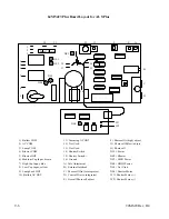
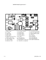
the correct position. There is an led on the P.C. Board that lights whenever
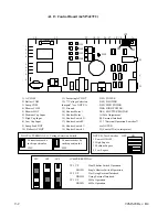
the shutter motor is being energized (see P.C. BOARD LAYOUT).
Shutter Switch
The switch provides shutter position information to the P.C. Board. This
switch is below the component chassis. A failure of the switch can cause
the shutter to rotate continuously or erratically. Similar problems may
be due to the shutter brake, the idle setting, or the P.C. Board.
The switch contacts close when the shutter is fully open and remains
closed until the shutter fully closes. This can be measured on the P.C.
Board (see P.C. BOARD LAYOUT). The switch is wired to the normally
open contacts and is adjustable. We recommend scribing a line around
the switch if replacement is necessary to return to the same position.
The switch roller should be centered on the cam and close when the cam
pushes the wheel on the switch halfway.
Shutter Motor
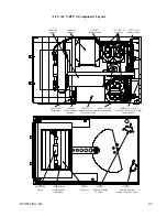
The shutter motor is located between the two sets of capacitors. We
recommend checking the power and signals from the switch and to the
motor coil before removing the motor. The motor operates from 9VDC
which comes from the P.C. Board. Should the motor want to travel past
its desired location and the shutter switch is operating properly the motor
brushes are most likely to be at fault and are replaced as follows.
Changing Shutter Motor Brushes
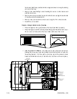
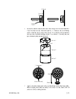
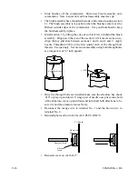
Should the shutter motor ever need replacement you will need a Phillips
screwdriver and a 5/32" Allen wrench.
•
Remove the safety glass and the cover (see AL 9/AL 13 COVER
REMOVAL).
•
Remove the two Phillips screws holding the shutter timing cam onto the
Summary of Contents for OLITE
Page 1: ...94MS20 Rev B4 OLITE OLITE 60Hz Printing Light Service Manual O...
Page 8: ...1 2 94MS20 Rev B4...
Page 20: ...3 10 94MS20 Rev B4...
Page 56: ...5 30 94MS20 Rev B4...
Page 86: ...7 22 94MS20 Rev B5...
Page 108: ...9 20 94MS20 Rev B4...


