9-16
94MS20 Rev. B4
•
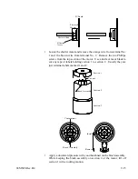
Slide brushes off the commutator. Slide new brush assembly onto
commutator. Note: Center hole on brush assembly must face up.
•
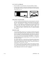
The brush assembly has a shoulder that rests on the motor housing (section
2). The brush assembly is in position when the brushes center over the
farthest outside edges of the commutator. Use your thumbnail to keep
the brush assembly in place.
•
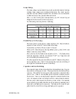
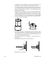
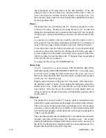
Install section 1 by tilting the cut-out so that it fits in behind the brush
assembly. Drop down the rest of the section 1 till it meets section two.
Align the key and slots between sections 1 and 2, and 2 and 3. Apply
Loctite Threadlock #242 on the first quarter inch of the through bolt
threads. Use sparingly. Secure motor assembly using both throughbolts
at a torque rate of 5-7 inch pounds.
Keyed Locations
± .010"
•
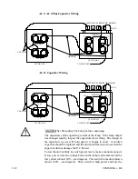
Once the through bolts are installed make sure the armature has about
.010" of play up and down. Using a pair of needle nose pliers, take hold
of the armature, move up and down and turn shaft both directions to be
sure it is and the armature moves freely.
•
Reconnect the orange wire to terminal No. 1 and the brown wire to
terminal No. 2.
•
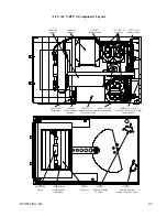
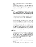
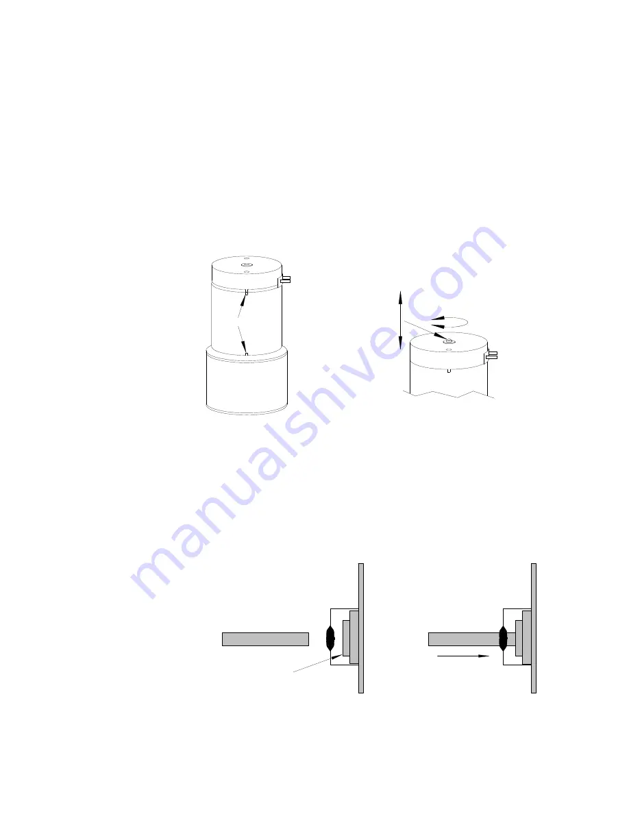
Reinstall photocell rod (AL9 & AL9 PLUS ONLY).
PC Board
Photocell
Mount
Photocell Rod
Filtration
layers
•
Reinstall cover on AL9/AL13
Summary of Contents for OLITE
Page 1: ...94MS20 Rev B4 OLITE OLITE 60Hz Printing Light Service Manual O...
Page 8: ...1 2 94MS20 Rev B4...
Page 20: ...3 10 94MS20 Rev B4...
Page 56: ...5 30 94MS20 Rev B4...
Page 86: ...7 22 94MS20 Rev B5...
Page 108: ...9 20 94MS20 Rev B4...

