94MS20 Rev. B4
5-3
Trigger Board
A trigger board is provided in the light head to start the lamp. This board
operates on demand by sensing the lamp voltage. This board can be heard
when it is functioning, although the sound is faint. By turning the unit on
and off, the sound can be compared during trigger and cool-down. In
both situations, the fans are running full speed. The fans may be disabled
by pulling the blue wire from terminal #5 to aid in determining if the
trigger board is functioning.
!
C
Use caution that the lamp doesn’t run without cooling.
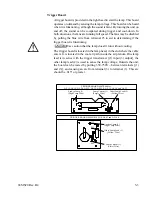
The trigger board is located in the lamp head, in the end where the cable
enters. It is located in the cool air path inside the air plenum. One lamp
lead is in series with the trigger transformer [(1) input (3) output], the
other lamp lead (2) is used to sense the lamp voltage. Outside the unit,
the board can be tested by putting 350-750V~ between terminals [(1)
and (3)], and causing an arc from terminal (3) to terminal (1). This arc
should be .015" or greater.
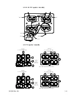
Lamp Current (1)
(Violet Wire)
Lead to Lamp (3)
(High Temp Wire)
Other Lamp Lead (2)
(Yellow Wire)
M2
M1
M3
TRIGGER BOARD #64MV414 FOR AL 83 and AL 100
TRIGGER BOARD #64TR408 for
AL 15, AL 19, AL 20, AL 23, AL 25, AL 25-2, AL 35, AL 50, and AL 53
Lead to Lamp (3)
(High Temp Wire)
Lamp Current (1)
(Purple Wire)
Other Lamp Lead (2)
(Yellow Wire)
Summary of Contents for OLITE
Page 1: ...94MS20 Rev B4 OLITE OLITE 60Hz Printing Light Service Manual O...
Page 8: ...1 2 94MS20 Rev B4...
Page 20: ...3 10 94MS20 Rev B4...
Page 56: ...5 30 94MS20 Rev B4...
Page 86: ...7 22 94MS20 Rev B5...
Page 108: ...9 20 94MS20 Rev B4...

