background image

94MS20 Rev. B4

0-3

7

Wiring Diagrams

Lamphead for AL  83, 84, 84-480, 85, 56, 56-480, 53, 54, 54-480,
55, 55-480, 50, 35, 25, 25-2, 23................................................... 7-1
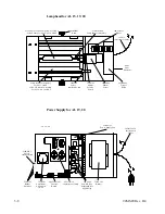
Lamphead for AL  100 ................................................................ 7-2
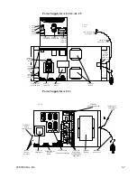
AL 83  Power Supply .................................................................. 7-3
AL 84,85  Power Supply ............................................................. 7-4
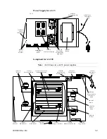
AL 84-480  Power Supply ........................................................... 7-5
AL 56  Power Supply .................................................................. 7-6
AL 56-480  Power Supply ........................................................... 7-7
AL 54,55  Power Supply ............................................................. 7-8
AL 54-480,55-480  Power Supply............................................... 7-9
AL 53 Power Supply ................................................................. 7-10
AL 50  Power Supply ................................................................ 7-11
AL 35  Power Supply  60Hz ...................................................... 7-12
AL 25-2  Power Supply ............................................................. 7-13
AL 25  Power Supply ................................................................ 7-14
AL 23  Power Supply ................................................................ 7-15
AL 20  Power Supply ................................................................ 7-16
AL 19  Power Supply ................................................................ 7-17
ALI 15  Power Supply ............................................................... 7-18
AL 15  Power Supply ................................................................ 7-19
Interconnect Cable for AL23, AL25, AL25-2, AL35, AL50, AL53,
AL83 .......................................................................................... 7-20
Interconnect Cable for AL85, AL84, AL84-480, AL56, AL56-480,
AL55, AL55-480, AL54, AL54-480 ......................................... 7-21

8

Fault Trees

No Strike Fault Tree .................................................................... 8-1
Shutter Rotation Fault Tree ......................................................... 8-2

9

AL 13 / AL 9

AL 13 Component Layout ........................................................... 9-1
AL 13 Control Board (64MV427C2) .......................................... 9-2
AL 13 (120V~) Wiring Diagram ................................................. 9-3
AL 13 (220V~) Wiring Diagram ................................................. 9-4
AL 9, AL 9-PLUS Component Layout ....................................... 9-5
64MV427-Plus Board Layout for AL 9-Plus .............................. 9-6
AL 9-Plus Wiring Diagram ......................................................... 9-7
64MV247 Board Layout for AL 9 ............................................... 9-8
AL 9 Wiring Diagram .................................................................. 9-9
AL 9, AL 13 Cover Removal .................................................... 9-10
Path of Power to the P.C.Board ................................................. 9-10
Interlock Systems ...................................................................... 9-10
Lamp Voltage ............................................................................ 9-11
Path Of Power To The Lamp ..................................................... 9-11
Capacitors and Level Switching ................................................ 9-11

Summary of Contents for OLITE

Page 1: ...94MS20 Rev B4 OLITE OLITE 60Hz Printing Light Service Manual O...

Page 2: ...is manual is designed for technical personnel and should only be used by authorized dealer service personnel This manual is written to provide an understand ing of the equipment as well as a plan for...

Page 3: ...Power Supply for AL 53 AL 50 3 5 Power Supply for AL 54 55 3 5 Power Supply for AL 54 480 55 480 3 6 Power Supply for AL 35 3 6 Power Supply for AL 25 2 AL 25 3 7 Power Supply for AL 23 3 7 Lamphead...

Page 4: ...AL 25 AL 25 2 Capacitor Assembly 5 10 AL 23 Capacitor Assembly 5 10 AL 20 AL 19 Capacitor Assembly 5 11 AL 15 Capacitor Assembly 5 11 Opening the Lamp Head 5 12 Shutter 5 12 Shutter Switch 5 13 Shutte...

Page 5: ...wer Supply 7 18 AL 15 Power Supply 7 19 Interconnect Cable for AL23 AL25 AL25 2 AL35 AL50 AL53 AL83 7 20 Interconnect Cable for AL85 AL84 AL84 480 AL56 AL56 480 AL55 AL55 480 AL54 AL54 480 7 21 8 Faul...

Page 6: ...9 13 Shutter Motor 9 13 Changing Shutter Motor Brushes 9 13 Steps to change shutter motor brushes 9 14 Idle Setting 9 17 Blower 9 18 Blown Fuse 9 18 Photocell 9 18 Photocell Rod Removal AL9 Only 9 19...

Page 7: ...3 lamphead only for the AL23 AL25 AL25 2 AL35 AL50 AL53 AL54 AL54 480 AL55 AL55 480 AL56 AL56 480 AL83 AL84 AL84 480 AL85 and AL100 power supply only for the AL100 units are very similar but some have...

Page 8: ...1 2 94MS20 Rev B4...

Page 9: ...of Health Before one becomes unduly concerned with the harm UV can cause it is important to understand the many beneficial effects connected with working outside and in bright areas with a certain am...

Page 10: ...ngs with even small parts of the lighted area of the lamp or the reflector visible during standby can be dangerous Such lights are best used within an enclosure that is shut completely at all times es...

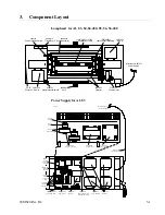
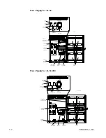
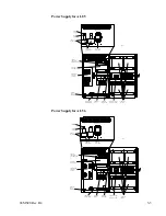
Page 11: ...Supply 62SA83 B Shutter Assembly PA91 Photocell 39BLO14 Reflector Power Supply for AL 83 Terminal Strip 18 1 Power Input Power Output 120 VAC Coil Voltage 32TRC03 Autoformer 33RLY18 Power Relay 33RLY0...

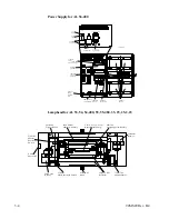
Page 12: ...KP01 Safety Interlock 62D2652A00 Capacitor Assembly 56FUS15 3Amp 250V 3AG Slow Blow Fuse 18 Terminal Strip 1 CL 84 Power Supply for AL 84 480 L1 T1 T2 L2 Power Power 120 VAC 33RLY04 33RLY02 32BAL01 52...

Page 13: ...toformer Capacitor Assembly Safety Interlock Control Board Blower Fuse Holder Ballast Selection Switch CL 85 Power Supply for AL 56 L1 T1 T2 L2 Power Power 120 VAC 33RLY04 33RLY02 32TRC08 32BAL01 52FU...

Page 14: ...US23 3Amp 250V 3AG Slow Blow Fuse L1 T1 T2 L2 33RLY04 Sealed Relays 33RLY02 Power Relay 18 Terminal Strip 1 2 1 CL 56 480 Lamphead for AL 53 54 54 480 55 55 480 35 25 25 2 23 64TR408 Trigger Board 62S...

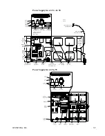
Page 15: ...oard 62D331 Voltage Selection Switch on older units L1 T1 T2 L2 33RLY18 Power Relay Terminal Strip 18 1 Power Input Power Output 120 VAC Coil Voltage 33RLY04 Sealed Relay Older AL50 units used just on...

Page 16: ...oard Blower Fuse Holder Ballast Power Supply for AL 35 32TRC01 Autoformer 56FUS15 3Amp 250V 3AG Slow Blow Fuse 52FUH04 Fuse Holder 32BAL01 Ballast 39BLO03 Blower 64MV407V03 Control Board 62D127 35 Cap...

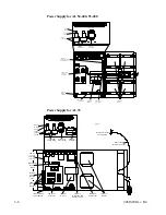
Page 17: ...64MV422 25 Resistor Board 62D331 Voltage Selection Switch on AL 25 2 units ONLY L1 T1 T2 L2 33RLY18 Power Relay Terminal Strip 18 1 Power Input Power Output 120 VAC Coil Voltage 33RLY04 Sealed Relay...

Page 18: ...tor Assembly For AL15 ONLY 62RA 1 Reflector Assembly For AL19 AL 20 ONLY 39BLO03 15 Blower L1150A or L1250E Lamp for AL15 ONLY L1250E Lamp for AL19 AL 20 ONLY Power Supply for AL 19 20 16D0334A18 Inte...

Page 19: ...head for AL 100 Note AL100 uses two AL53 power supplies 45KOB05 Knob 64MV414 Trigger Board 64MV414 Trigger Board 55SW02 Shutter Position Switch 31MOT06 Shutter Motor 39BLO03 Blower 16D334 Interconnect...

Page 20: ...3 10 94MS20 Rev B4...

Page 21: ...BALLAST 2 BALLAST 1 COM 208 CAP 240 CAP 240 208 COM 16 18 17 15 14 13 12 11 10 9 8 7 6 5 4 3 2 1 AC IN 6 GA BLK D3328A AL 84 85 Ballast Tap Switch Wiring AUTOFORMER 240 VOLT RED TO FUSE YELLOW TO AUTO...

Page 22: ...K RED 16 18 17 15 14 13 12 11 10 9 8 7 6 5 4 3 2 1 CONTACTOR AL 56 Ballast Tap Switch Wiring COM 208 240 CAP 240 CAP 208 COM BALLAST 1 BALLAST 2 L1 ORANGE TO CAP PACK L2 T1 T2 RED BLK CAP 240 208 COM...

Page 23: ...9 8 7 6 5 4 3 2 1 RED BALLAST 2 BALLAST 4 BALLAST 3 CONTACTOR AL54 AL55 Ballast Tap Switch Wiring COM 208 240 CAP 240 CAP 208 COM BALLAST 1 BALLAST 2 L1 ORANGE TO CAP PACK L2 T1 T2 RED BLK CAP 240 208...

Page 24: ...BLK RED 16 18 17 15 14 13 12 11 10 9 8 7 6 5 4 3 2 1 RED CONTACTOR AL53 50 Ballast Tap Switch Wiring TERMINAL STRIP CONTACTOR BLK RED 16 18 17 15 14 13 12 11 10 9 8 7 6 5 4 3 2 1 VIOLET RED BLK VOLTA...

Page 25: ...ER 240 VOLT TERMINAL STRIP CONTACTOR BLK RED ORANGE TO CAP PACK BALLAST 2 BALLAST 1 COM 208 CAP 240 CAP 240 208 COM 1 2 3 4 5 6 7 8 9 10 11 12 13 14 15 17 18 16 D3328A AL23 and AL20 Ballast Wiring 240...

Page 26: ...4 6 94MS20 Rev B4 AL 19 and AL15 Ballast Wiring 120 CAP COM BALLAST WHITE BLK CONTACTOR TERMINAL STRIP VIOLET ORANGE TO CAP PACK AC IN BLK RED 16 18 17 15 14 13 12 11 10 9 8 7 6 5 4 3 2 1...

Page 27: ...lters short UV radiation and covers the high voltage lamp terminals This interlock also protects from overheating by traveling through two thermostats in the lamp head There is also an outlet on some...

Page 28: ...1 2 0 0 1 9 5 1 9 5 2 3 5 5 0 0 6 5 9 0 60 85 1 0 0 1 2 5 110 125 A L 5 0 w L 1 2 5 0 1 9 0 1 8 5 2 7 0 5 0 0 6 0 9 0 110 125 110 125 A L 5 0 w L 1 2 5 2 2 0 7 2 0 0 2 7 0 5 0 0 6 5 9 0 110 125 110 12...

Page 29: ...he trigger board is located in the lamp head in the end where the cable enters It is located in the cool air path inside the air plenum One lamp lead is in series with the trigger transformer 1 input...

Page 30: ...power In all lights the medium relay will also always pull in for high power exposures The capacitors set the operating current of the lamp If the lamp output has changed rapidly inspect the capacitor...

Page 31: ...BROWN 3 BLUE 4 BLUE WITH WHITE STRIPE 5 ORANGE CAPACITOR ASSEMBLY PART 62D2652A00 12 12 10 16 2 1 4 3 5 5 AL 84 480 Capacitor Assembly 5 WIRE COLORS 1 YELLOW 2 BROWN 3 BLUE 4 BLUE WITH WHITE STRIPE 5...

Page 32: ...CAPACITORS FRONT VIEW BOTTOM VIEW BLUE WHITE 2 BLUE 3 BROWN 4 YELLOW 5 ORANGE 64MV422V00 4 1 3 2 1 4 4 C1 C2 C4 5 5 5 C3 2 3 C5 5 REMOVE 14 AWG ORANGE WIRE FROM BALLASTS AL 56 Capacitor Assembly 5 4 2...

Page 33: ...CITOR ASSEMBLY 62D3083A00 10 10 5 5 2 4 1 3 AL 54 AL 55 Capacitor Assembly DO NOT SWITCH WHILE UNIT IS ON CAUTION 2 1 5 5 5 4 3 2 1 1 2 3 WIRES FROM HARNESS WIRES TO CAPACITOR TOP FRONT VIEW OF PC BOA...

Page 34: ...GE 6 BLACK 12 CAPACITOR ASSEMBLY PART 62D3654A00 SWITCH ON CAPACITOR MOUNTING BRACKET 4 3 2 1 REAR VIEW OF PC BOARD 6 3 1 12 10 12 AL 53 AL 50 Capacitor Assembly Capacitor Assembly 62D127 Blue White 1...

Page 35: ...2 2 5 4 5 4 8 8 8 8 8 8 8 2 2 5 4 5 4 2 Old Style AL 53 Old Style AL 50 AL 35 Capacitor Assembly Capacitor Assembly 62D127 35 YELLOW 5 5 2 BLACK 3 2 4 1 Blue White 1 Wire Colors 2 3 4 Blue Brown Yello...

Page 36: ...D126 New Style Old Style 2 1 Blue Yellow 3 Orange Wires to Capacitors FRONT PCB 2 1 12 12 8 8 8 3 1 2 3 2 1 1 3 AL 23 Capacitor Assembly 3 9 1250 1261 1250 1261 12 BROWN 12 12 9 3 BLUE YELLOW ORANGE 2...

Page 37: ...FROM HARNESS 1 3 5 5 1 3 Old Style AL 15 with L1150A Lamp WIRES FROM HARNESS 1 3 5 3 5 7 CAPACITOR ASSEMBLY PART 62D139 New Style AL 15 with L1150A Lamp Old Style AL 15 with L1150B Lamp 8 16 8 8 8 8...

Page 38: ...thead Bottom View Top View Remove the 6 screws from each side of the lamphead and remove the two endcaps On 8kW lampheads you can now access the trigger board and shutter position switch that are loca...

Page 39: ...from terminal 9 to terminal 7 The level is 12 VDC when the shutter is closed and 0 V when the shutter opens The switch is in the lamp head on the end where the cable enters inside the air manifold on...

Page 40: ...r end of the light Remove the chain from the sprocket with care to keep tension The chain has shortened links and will separate if slackened If the chain opens attach an end to the sprocket with tape...

Page 41: ...mp support assembly makes this easier END VIEW Remove the 4 screws holding the rear reflector to the air tubes and remove the reflector and lamp from the lamphead C DO NOT TOUCH THE REFLECTOR SURFACE...

Page 42: ...PN HD 8 WASHER SPLIT LOCK 2 6 WASHER SPLIT LOCK ITM 9 1 2 3 4 5 6 7 8 PART NO DESCRIPTION D3214B 6 X 180 ROUND SPACER 42HHS8500 11D886 REFLECTOR INNER RF53 1 1 11D2206 SHUTTER ASSEMBLY LT1 12D2060A07...

Page 43: ...the reflector and lamp from the lamp head C DO NOT TOUCH THE REFLECTOR SURFACE WITH YOUR HANDS Bottom View Remove the three screws from the blower mounting plate to the cooling tubes on both sides Com...

Page 44: ...W 100 FLAT HD 2 3 6 WASHER LOCK INTERNAL 41 06WLI 63D0142B03 LAMP SUPPORT ASSEMBLY 2 IDLER ARM SHUTTER 63D3530A62 4 SHUTTER END PHOTOCELL SLOT QTY 11D3974A71 2 1 11D0210A62 TIMING DISC LT 1 12D1873A62...

Page 45: ...period of time Successive rapid exposures would not fail since it takes many minutes for the unit to over cool This over cooling situation could also be due to a bad idle capacitor which would not al...

Page 46: ...d check if the fuse is a 5 amp fuse The printed circuit board drives five or six circuits the lamp head blowers shutter motor power supply blower and the relays To find the cause Unplug the unit and r...

Page 47: ...no current 2 3 Lamp terminals 2 and 3 carry the power to the lamp If the lamp is hot or fails to start the voltage should be 600 to 950V During this time there are voltage pulses that may damage a se...

Page 48: ...to the printed circuit board This switch is open when the shutter is closed and closes when the shutter opens This signal is low voltage DC and can be measured on terminal 9 on terminal 7 The meter wi...

Page 49: ...the lamp fans vary in speed to maintain the proper lamp temperature This allows the unit to consume less power on idle and provides a wider range of exposure capabilities since this same low power lev...

Page 50: ...Main Contactor High Relay Medium Relay Shutter Motor K1 TR101 TR102 TR103 TR104 P1 Power Connector 6 5 4 3 2 1 AC Hot AC Common Lamp Fans Shutter Motor High Relay Medium Relay 11 7 8 9 10 12 Unit Fan...

Page 51: ...e the main relay This provides power to the lamp circuit P9 Not currently used P10 Aux Terminal connects to the signal connector for accessories Not used in most equipment P11 DC Common Circuit common...

Page 52: ...rnal accessories Not used in most equipment DIN Connection D1 Expose High expose when connected to a compatible integrator High Medium Low expose depending on the unit switches when connected to an ol...

Page 53: ...cted Aux Terminal High Relay Shutter Position DC Common 110 VAC AC Common Lamp Fans Shutter Motor Connector P1 12 V Power Supply Output for Lamp Blowers D18 U4 U5 Output for High Relay D15 Q4 K3 Outpu...

Page 54: ...rd has a serial number below those just stated you have an older board Note This pertains only to the models mentioned and no others 14 1 Lamp Signal Connector LED s 1 2 3 4 Low Expose Control Board c...

Page 55: ...110V output to power on off switch P7 High Low Switch 110V output to high low intensity switch Switch must be at high power to be controlled externally from an integrator P8 Power Relay V Output to dr...

Page 56: ...5 30 94MS20 Rev B4...

Page 57: ...in the light source is going to draw excess amperage as voltage goes down amperage draw has to go up If when you open the power supply you notice right off burnt wires or connectors one of the most li...

Page 58: ...if the light source comes on turn power off immediately and determine what is shorting out and bypassing the safety interlock circuit If this does happen it is possible that the safety interlock circu...

Page 59: ...ver any of the wiring between ballast and tap switch is suspect If the voltage is zero then a burnt wire at the power relay or a bad power relay is most likely the problem There is a possibility that...

Page 60: ...P ORANGE YELLOW BLUE a IDLE LOW 500 190 500 b HIGH 500 230 230 1 9kW and 2kW other than AL25 and AL25 2 with L1150A LAMP ORANGE YELLOW BROWN BLUE a IDLE 500 205 500 500 b LOW 500 190 500 500 c MEDIUM...

Page 61: ...YELLOW BROWN BLUE a IDLE LOW 500 200 500 500 b MEDIUM 500 215 215 500 c HIGH 500 240 240 240 3 5kW with L1252 or L1261 LAMP ORANGE YELLOW BROWN BLUE a IDLE LOW 500 195 195 500 b HIGH 500 230 230 230...

Page 62: ...LUE 1 BLUE 2 a IDLE 700 360 700 700 700 b LOW 700 360 700 700 700 c MEDIUM 700 390 390 700 700 d HIGH 700 425 425 425 425 8kW with L1281 LAMP ORANGE YELLOW BROWN BLUE 1 BLUE 2 a IDLE 700 395 700 700 7...

Page 63: ...austs If any are found remove them 15 Check lamp idle voltage at terminals 2 3 This voltage should match the voltage chart above if not YOU MUST install a new lamp and recheck see Idle Setting if adju...

Page 64: ...correct position 23 If the shutter stops immediately but in the wrong position check the shutter position switch 24 If the shutter coasts to a stop in the wrong position check the shutter brake 25 If...

Page 65: ...Diagrams Lamphead for AL 83 84 84 480 85 56 56 480 53 54 54 480 55 55 480 50 35 25 25 2 23 12 10 8 6 4 2 Shutter Position Switch 11 9 7 5 3 1 Shutter Motor Lamp Trigger Board Blowers Thermostat Therm...

Page 66: ...uses two AL 53 power supplies 1 2 3 4 5 6 7 8 9 10 11 12 Shutter Position Switch Safety Glass Switch Thermostats Thermostats Shutter Motor Blowers Blowers 2 4 6 8 10 12 1 3 5 7 9 11 1 3 5 7 9 11 2 4...

Page 67: ...ast 11 9 7 5 3 1 12 10 8 6 4 2 Interconnecting Beau Plug Connector 2 Position 1 Medium Relay 10 COM COM 1 2 3 4 5 6 7 8 9 10 11 12 1 2 3 4 5 6 7 8 9 10 11 12 P O W E R C O N T R O L B O A R D P2 P1 18...

Page 68: ...8 brn 7 org 6 red 5 blu 4 wht 3 pur 2 yel 1 grn yel Power Relay P O W E R S U P P L Y T E R M I N A L S T R I P Voltage Selection Board 240 208 208 120 0 Ballast High Relay 220 VAC 50HZ INPUT 3 Amp S...

Page 69: ...13 wht 12 red 11 10 blk 9 clear 8 brn 7 org 6 red 5 blu 4 wht 3 pur 2 yel 1 grn yel Power Relay P O W E R S U P P L Y T E R M I N A L S T R I P 277 277 Ballast High Relay 480 VAC 60HZ INPUT P O W E R...

Page 70: ...brn 7 org 6 red 5 blu 4 wht 3 pur 2 yel 1 grn yel Power Relay P O W E R S U P P L Y T E R M I N A L S T R I P Voltage Selection Board 240 208 240 208 240 208 120 0 Tap Switch Ballast High Relay 208 24...

Page 71: ...k 13 wht 12 red 11 10 blk 9 clear 8 brn 7 org 6 red 5 blu 4 wht 3 pur 2 yel 1 grn yel Power Relay P O W E R S U P P L Y T E R M I N A L S T R I P Ballast High Relay 480 VAC 60Hz INPUT P O W E R C O N...

Page 72: ...g 6 red 5 blu 4 wht 3 pur 2 yel 1 grn yel Power Relay P O W E R S U P P L Y T E R M I N A L S T R I P Voltage Selection Board 240 208 240 208 240 208 120 0 Tap Switch Ballast High Relay 208 240 V INPU...

Page 73: ...blk 13 wht 12 red 11 10 blk 9 clear 8 brn 7 org 6 red 5 blu 4 wht 3 pur 2 yel 1 grn yel Power Relay P O W E R S U P P L Y T E R M I N A L S T R I P Ballast High Relay 480 VAC 60Hz INPUT P O W E R C O...

Page 74: ...ower Supply Blower Ballast 11 9 7 5 3 1 12 10 8 6 4 2 Interconnecting Beau Plug Connector 2 Position 1 Medium Relay COM COM 18 17 16 15 14 blk 13 wht 12 red 11 10 blk 9 clear 8 brn 7 org 6 red 5 blu 4...

Page 75: ...wer Ballast 11 9 7 5 3 1 12 10 8 6 4 2 Interconnecting Beau Plug Connector 2 Position 1 High Relay COM COM 18 17 16 15 14 blk 13 wht 12 red 11 10 blk 9 clear 8 brn 7 org 6 red 5 blu 4 wht 3 pur 2 yel...

Page 76: ...7 5 3 1 12 10 8 6 4 2 Interconnecting Beau Plug Connector Medium Relay 2 Position 1 12 16 8 16 COM COM 1 2 3 4 5 6 7 8 9 10 11 12 1 2 3 4 5 6 7 8 9 10 11 12 P O W E R C O N T R O L B O A R D P2 P1 18...

Page 77: ...last 11 9 7 5 3 1 12 10 8 6 4 2 Interconnecting Beau Plug Connector 12 12 COM COM 1 2 3 4 5 6 7 8 9 10 11 12 1 2 3 4 5 6 7 8 9 10 11 12 P O W E R C O N T R O L B O A R D P2 P1 18 17 16 15 14 blk 13 wh...

Page 78: ...connecting Beau Plug Connector 12 12 COM COM 1 2 3 4 5 6 7 8 9 10 11 12 1 2 3 4 5 6 7 8 9 10 11 12 P O W E R C O N T R O L B O A R D P2 P1 18 17 16 15 14 blk 13 wht 12 red 11 10 blk 9 clear 8 brn 7 or...

Page 79: ...er Supply Fan Medium Relay CAP COM 2 1 12 3 9 9 12 12 3 1 2 Position Position 1 2 3 4 5 6 7 8 9 10 11 12 1 2 3 4 5 6 7 8 9 10 11 12 P O W E R C O N T R O L B O A R D P2 P1 18 17 16 15 14 blk 13 wht 12...

Page 80: ...n Medium Relay CAP COM 10 10 9 10 3 2 1 Position 10 9 8 7 6 5 4 3 2 1 L A M P H E A D T E R M I N A L S T R I P Safety Glass Switch Thermostat Shutter Position Switch Shutter Motor Trigger Board Blowe...

Page 81: ...T R O L B O A R D Power Supply Fan Medium Relay CAP COM 10 10 9 10 3 2 1 Position 10 9 8 7 6 5 4 3 2 1 L A M P H E A D T E R M I N A L S T R I P Safety Glass Switch Thermostat Shutter Position Switch...

Page 82: ...rd front of unit Toward center of unit gry org brn red wht org wht brn wht blu wht red blu wht blk wht blu Safety Glass Switch Power High Expose Safety Interlock 120 Ballast High Relay Power Relay 120...

Page 83: ...1 grn yel Toward front of unit Toward center of unit gry org brn red wht org wht brn wht blu wht red blu wht blk wht blu Safety Glass Switch Power High Expose Safety Interlock 120 Ballast High Relay P...

Page 84: ...ct Cable for AL23 AL25 AL25 2 AL35 AL50 AL53 AL83 1 2 4 3 6 5 8 7 10 9 12 11 WHITE GREEN VIOLET BLUE ORANGE BLACK YELLOW RED BROWN HEAT SHRINK 1 GREEN 2 YELLOW 3 VIOLET 4 WHITE 5 BLUE 6 RED 7 ORANGE 8...

Page 85: ...85 AL84 AL84 480 AL56 AL56 480 AL55 AL55 480 AL54 AL54 480 1 2 4 3 6 5 8 7 10 9 12 11 WHITE GREEN VIOLET BLUE ORANGE BLACK YELLOW RED BROWN HEAT SHRINK 1 2 4 3 6 5 8 7 10 9 12 11 WHITE GREEN VIOLET BL...

Page 86: ...7 22 94MS20 Rev B5...

Page 87: ...Is there 0 VAC across pins 4 and 10 Replace PCB Verify operation Repair or replace wires Verify operation Check wiring from voltage selector assy through ballasts to capacitors Verify operation Repla...

Page 88: ...or bearings worn Yes Yes No Yes Adjust shutter motor and or replace bearings and air tubes Yes Possible faulty shutter motor No No Check for 120 VAC on terminal 4 white and terminal 6 red on the termi...

Page 89: ...03 Blower 56THM03 Thermostat 55SW02 Safety Interlock Switches 64MV461V00 Resistor Board 93MV427C2 Control Board 63D0142B02 Lamp Support Assembly L900 L902 Lamp 90RF13 Reflector 55SW02 1 Safety Interlo...

Page 90: ...OTOR A Idle Adjustment B External Interlock C External Operation Switches see NOTE B D Control Din to integrator NOTE A TERMINAL 12 Voltage Selection Switch Connector must be in this position for 120V...

Page 91: ...DRIVE 12VDC 31MOT11 39BLO03 MOTOR BLOWER M2 SWITCH SHUTTER 55SW02 1 34CAP18 S C2 C4 CAPACITOR 20 400V SW3 SW4 J12 120V 220V J8 J7 J6 J5 J9 4 1 P1 2 P1 1 YEL R2 C2 C1 R1 BLK RED BLK R8 R7 R6 R5 SW4 SW...

Page 92: ...MOTOR BLOWER M2 SWITCH SHUTTER 55SW02 1 FUSE 4 AMP 250V SB FUSE 34CAP18 S C2 C3 C4 CAPACITOR 20 F 400V BLU BRN YEL 220V COM CAP BLK RED ORG HI VOLT GRN YEL BLU BRN RED BLK ORG HI VOLT YEL YEL YEL ORG...

Page 93: ...rmostat 55SW02 Safety Interlock Switches 64MV461V00 Resistor Board 64MV427 T for AL 9 Control Board 63D0142B02 Lamp Support Assembly L900 ONLY Lamp 90RF13 Reflector 55SW02 Shutter Position Switch 64CT...

Page 94: ...Not Used 14 Shutter Switch 15 Shutter Switch 16 Ground A Idle Adjustment B External Interlock C Photocell Din to integrator D Control Din to integrator E Overall Photocell adjust F Photocell A high a...

Page 95: ...CAPACITORS BALLAST CHASSIS GROUND INCOMING AC COM SHUTTER MOTOR SAFETY GLASS SWITCH THERMOSTAT INCOMING AC HOT SAFETY GLASS SWITCH 15 f 15 f 15 f 15 f SHUTTER POSITION SWITCH 1 SHUTTER POSITION SWITC...

Page 96: ...HOT 12 Shutter Motor 13 Shutter Motor 14 Shutter Switch 15 Shutter Switch 16 Ground A Idle Adjustment B External Interlock C Photocell Din to integrator D Control Din to integrator E Overall Photocel...

Page 97: ...1 2 3 14 15 16 9 8 7 4 5 6 LAMP LOW MED HIGH BLOWER CAPACITORS BALLAST CHASSIS GROUND INCOMING AC COM SAFETY GLASS SWITCH THERMOSTAT INCOMING AC HOT SAFETY GLASS SWITCH 15 f 15 f 15 f 15 f SHUTTER POS...

Page 98: ...C Board as incoming V common Interlock Systems The internal interlock system serves two purposes The first is for operator safety by protecting the safety glass This glass filters short UV radiation...

Page 99: ...M This is the feed to the ballast and should be 120 V The ballast then feeds the capacitors with the wire labeled CAP see Capacitors and Level Switching for detailed wiring From the capacitors the pow...

Page 100: ...of the lamp If the lamp output has changed rapidly inspect the capacitors for swelling The design of the capacitors we use will burn open if it begins to short A swollen capacitor should be replaced a...

Page 101: ...the switch can cause the shutter to rotate continuously or erratically Similar problems may be due to the shutter brake the idle setting or the P C Board The switch contacts close when the shutter is...

Page 102: ...rushes Place the light on its top and remove the hood and filter assembly Place the light on a table with the shutter flat against the table and remove the two screws from each of the four sides and r...

Page 103: ...top section of the motor Use a knife or razor blade to cut any tape or labels holding section 1 to section 2 Usually they are just terminal labels marked 1 and 2 Brush Assembly Cut out Section 1 Sect...

Page 104: ...n two Align the key and slots between sections 1 and 2 and 2 and 3 Apply Loctite Threadlock 242 on the first quarter inch of the through bolt threads Use sparingly Secure motor assembly using both thr...

Page 105: ...again for several seconds before finishing the exposure This should only happen if the unit is left for a period of time Successive rapid exposures would not fail since it takes many minutes for the u...

Page 106: ...Blown Fuse The P C board drives several circuits THE BLOWER SHUTTER MOTOR and the SHUTTER POSITION SWITCH To find the cause of a blown fuse unplug the light and remove the cover see Cover Removal Dis...

Page 107: ...ding is done as follows Remove the safety glass and the cover see COVER REMOVAL Place the AL 9 AL 13 on a non flammable surface C DO NOT PLACE ON WOOD CARPET OR ANY SURFACE AFFECTED BY HEAT Bypass the...

Page 108: ...9 20 94MS20 Rev B4...

Page 109: ...p for thermostat 2 63D3530A62 Idler Arm Shutter 2 90GEARKIT Motor and shutter sprokets 1 AL 85 POWER SUPPLY 8kW 208 240V 62CL85 CL85 Power Supply 16D1045A00 Harness Beau Plug OEM 1 16D1585 Interlock H...

Page 110: ...O 30A 1 33RLY04 Relay Sealed 2 39BLO03 Blower Model Ball Bearing 1 52FUH04 Fuse Holder 3AG 3AB 1 54PWR05 Pwr Crd 18 3 SJT 12 5 15 1 56FUS15 Fuse 3A 250V 3AG Slow Blow 1 62D3533A00 Assy Capacitor 60H 4...

Page 111: ...ass y 8kW SE 1 11D0210A62 Timing disc LT 1 1 12D1873A62 Air Tube Drive Rear 1 12D1874A62 Air Tube Front 1 12D2060A07 Spring shutter AL 83 2 12D3515A00 Ball bearing 6 12D3550A62 Bushing Idler Arm 2 43...

Page 112: ...hutter Position Switch 1 55SW03 Switch Glass 2 Pos Blk 1 56THM01 Thermostat model K 2 62SASE Shutter ass y 5kW SE 1 11D0210A62 Timing disc LT 1 1 12D2060A07 Spring shutter AL 83 2 12D3515A00 Ball bear...

Page 113: ...250V 3AG Slow Bl 1 62D127 Capacitor Assy AL 50 53 1 34CAP12 HV Capacitor 12 1200 V 2 34CAP16 HV Capacitor 16 1200 V 2 55SW01 Switch CW 1 64MV422V00 Resistor board AL 53 50 50 1 62D331A Voltage Selecto...

Page 114: ...1 32TRC01 Autoformer 208 240 V 1 33RLY02 Contactor 2 pole NO 30 1 33RLY04 Relay Sealed 1 52TS18 Terminal Strip 18 position 1 64MV407V03 Assy UV Lt Ctrl 5kW 60Hz 1 AL 25 POWER SUPPLY 2kW 120V 62CL25 1...

Page 115: ...1 AL 20 POWER SUPPLY 2kW 208 240V 62CL20 AL 20 2kW Power Supply 1 32BAL01 Ballast AL 15 53 1 32TRC01 Autoformer 208 240 V 1 44LEG03 Leveling Glide Non Skid 4 54PWR04 Pwr Crd 14 3 SJT 6 6 15P 1 62D137...

Page 116: ...oller 2 55SW12 Switch AL 9 2 56THM03 Thermostat 90 C 1 62D969 AL 13 14 Link Assembly 1 63D0142B02 AL 13 14 Lamp Support Assy 2 64MV427C2 T AL 13 15 PCBA 1 64MV461V00 Assy Resistor PCB AL13 14 1 AL 13...

Page 117: ...uipment It is the Buyer s responsibility to ascertain the suitability of the equipment for the application The Buyer assumes all risk and responsibility for the proper installation for reading the Ins...

Page 118: ...O Corporation 1850 East Saint Andrew Place Santa Ana Ca 92705 U S A Tel 714 258 5600 Fax 714 258 5601...

Reviews: