26
GB
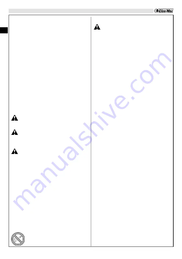
FUELING
WARNING: Gasoline is an extremely
flammable fuel. Use extreme caution when
handling gasoline or fuel mix. Do not smoke
or bring any fire or flame near the fuel or the
unit.
·
To reduce the risk of fire and burn injury,
handle fuel with care. It is highly flammable.
·
Mix and store fuel in a container approved for
gasoline.
·
Mix fuel outdoors where there are no sparks or
flames.
·
Select bare ground, stop engine, and allow to
cool before refueling.
·
Loosen fuel cap slowly to release pressure and
to keep fuel from escaping around the cap.
·
Tighten fuel cap securely after refueling. Unit
vibration can cause an improperly tightened
fuel cap to loosen or come off and spill
quantities of fuel.
·
Wipe spilled fuel from the unit. Move 3 metre
away from refueling site before starting
engine.
·
Never attempt to burn off spilled fuel under
any circumstances.
·
Do not smoke while handling fuel or while
operating the unit.
·
Store fuel in a cool, dry, well ventilated place.
·
Never place the machine in a combustible
area such as dry leaves, straw, paper, etc.
·
Store the unit and fuel in an area where fuel
vapors cannot reach sparks or open flames
from water heaters, electric motors or
switches, furnaces, etc.
·
Never take the cap off the tank when the
engine is running.
·
Never use fuel for cleaning operations.
·
Take care not to get fuel on your clothing
This product is powered by a 2-cycle engine and
requires pre-mixing gasoline and 2-cycle oil.
Pre-mix unleaded gasoline and 2-cycle engine
oil in a clean container approved for gasoline.
RECOMMENDED FUEL:
THIS ENGINE IS
CERTIFIED TO OPERATE ON UNLEADED
GASOLINE INTENDED FOR AUTOMOTIVE USE
FITTING THE SAFETY GUARD (Fig.7)
- Insert the two pins (E) of the cutting attachment
guard, in the holes (F).
- Fit the blade guard (A) to the shaft arm with screws
in a position allowing the operator to work safely
(B).
NOTE: use the guard (C) only with nylon head.
Secure the guard (C) to the protection (A) by
means of the screw (D).
FITTING THE DISK (Fig. 9)
Loosen the bolt (A) clockwise; remove washer (B),
cup (D) and lower flange (E).
Fix the blade (R) onto the upper flange (F) making
sure that the rotation direction is correct.
Fix the lower flange (E), the cup (D), the washer (B)
and tighten bolt (A) anti-clockwise.
Put the pin provided in the appropriate hole (L) to
block the blade and allow the bolt (A, Fig. 2) to be
tightened to
2.5 kgm (25 Nm).
WARNING – Collar (see arrows C, Fig.9)
must locate in blade’s mounting hole.
WARNING!
This machine is not suitable for
use with blade for wood (22-60-80 teeth) and
relevant metal guard.
WARNING: Make sure that all components
are connected properly and all screws tightened.
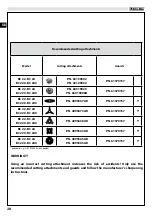
Approved power tool attachments (Fig.19)
The following Emak attachments may be mounted
to the basic power tool:
EH 24
Hedge trimmer (adjustable)
(1) (2)
EH 48
Hedge trimmer (adjustable)
(1) (2)
EP 100
Pole pruner
(2)
(1)
Safety boom (A, Fig.9A) must be assembled
under the loop handle.
(2)
Not approved for use with bike handle units
(BC
220 T – BC 240 T)
.
5. STARTING
Summary of Contents for BC 22 TR
Page 1: ......
Page 2: ......
Page 3: ......
Page 4: ......
Page 5: ......
Page 147: ...GR 143 8 158 9 10 11 12 13 14 15 16 25 17 149 18 19 20 21 1 2 3 4 5 6 15 7...
Page 153: ...GR 149 6 18 1 17 STOP 7 A Y...
Page 154: ...GR 150 1 2 3 4 5 15...
Page 155: ...GR 151 2 5 kgm 25 Nm 4 5 m 75 m 8 12 1 2...
Page 156: ...GR 152 15 16 8 3 p n 4196086 3 10 12 cm 14...
Page 160: ...GR 156 23 11 EKTAKT YNTHPH 10 A O 148...
Page 165: ...GR 161 15 1 2 1 CMR7H 2 148 1 2 3 1 2 3 T 21 1 1...
Page 213: ...RUS UK 209...
Page 214: ...RUS UK 210 2 3 4 5 15 1...
Page 215: ...RUS UK 211 8 12 1 2 2 5 kgm 25 Nm 4 5 75...
Page 216: ...RUS UK 212 10 12 14 15 16 8 A C O O A P c 3 p n 4196086 3...
Page 220: ...RUS UK 216 10 XPAHEH E o e a o a a a o e e o a e o a e e a o o o a o e o o a e a 208 23 11...
Page 225: ...RUS UK 221 15 1 2 1 cmr7h 2 208 1 2 3 1 2 2 3 T 21 1 1...
Page 246: ......


