background image

28

OLEO INTERNATIONAL

LB 50-65

11

10

9

8

7

6

5

4

3

2

1

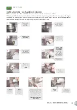
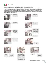
Posizio

n

are

l’i

n

terr

u

ttore e le

viti

Tappo 

d

i plastica

ri

m

osso e

s

m

altito

Gr

u

ppo staffa 

d

i

posizio

n

a

m

e

n

to

i

n

 posizio

n

Alli

n

eare la staffa

co

m

m

ostrato

Fissare il 

d

a

d

o

sal

d

a

m

e

n

te alla g

u

i

d

a,

applicare il fre

n

afiletti

(es. Loctite 242/243)
stri

n

gere il 

d

a

d

o co

n

coppia 

d

i serraggio 

d

i

10 N

m

 (8 ft/lbs)

Tappo e ro

nd

ella

pri

m

d

el

m

o

n

taggio

Ro

nd

ella ri

m

ossa

e s

m

altita

Spi

n

gere la leva

i

n

 ava

n

ti fi

n

o a

toccare l’asta 

d

i

spi

n

ta

Gr

u

ppo staffa i

n

posizio

n

e al 

d

i

sopra 

d

el co

d

olo

filettato

Leva che

tocca

legger

m

e

n

te

l’asta 

d

i

spi

n

ta

Leva che tocca

legger

m

e

n

te lo

sta

n

t

u

ffo

d

ell’i

n

terr

u

ttore

Co

n

 il fi

n

ecorsa posizio

n

ato e

fissato i

n

 posizio

n

e co

m

e

i

nd

icato i

n

 fig. 9, ri

mu

overe la

copert

u

ra 

d

el 

n

astro a

d

esivo,

pre

m

ere co

n


d

ecisio

n

e il

sottopiastra co

n

tro la staffa,

lascia

nd

o f

u

ori

u

scire le 

du

e viti

I

n

serire le 

du

e ro

nd

elle e 

d

a

d

i

per fissare l’i

n

terr

u

ttore

Ro

nd

ella e

d

a

d

o

Gruppo

interruttore

montato

correttamente

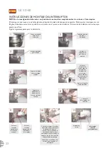
ISTRUZIONI DI MONTAGGIO DEL GRUPPO INTERRUTTORE

Nota: l’ammortizzatore deve essere in posizione completamente estesa prima di montare l’interruttore.

L interruttore viene fornito all interno di una busta di plastica, che viene fissata con del nastro adesivo sul lato del serbatoio
di espansione. Dal momento che gli interruttori sono fragili questi dovrebbero essere installati il più tardi possibile durante il
processo di montaggio, e sicuramente dopo che tutte le altre attrezzature pesanti siano state installate nel pozzo dell ascensore.
Seguire le fasi seguenti per l installazione:

Summary of Contents for LB 50

Page 1: ...ELEVATOR LB 50 65 INSTALLATION GUIDE GUIDE D INSTALLATION MONTAGEANLEITUNG GUIA DE INSTALA O GU A DE INSTALACI N GUIDA ALL INSTALLAZIONE...

Page 2: ...r PREPARATION FOR INSTALLATION The Oleo elevator buffer is supplied with a sealed gas precharge the plunger is held in the fully compressed condition during transportation by means of a wire rope and...

Page 3: ...ill the unit with oil the approximate volume is stated in table 1 e Take care when handling the oil and observe the oil manufacturers recommendations f Allow to stand for 30 minutes then check oil lev...

Page 4: ...Plastic cap removed and discarded Position bracket assembly in position Square up bracket as shown Fit nut securely to guide apply thread lock eg Loctite 242 243 tighten nut to 10Nm 8 ft lbs Cap and w...

Page 5: ...OSITION 99 NITROGEN 1 INERT TRACER SF6 BSI LB 002 NETEC NY MEA 54 08 M CA 4648 OIL SPECIFICATIONS VISCOSITY INDEX 75 MINIMUM VISCOSITY 280 350 SSU AT 100 F 38 C OR ISO VG68 68mm s AT 40 C EN81 1 POUR...

Page 6: ...res 8 8 gallons 73 0 litres 19 3 gallons 117 0 litres 30 9 gallons Buffer Mass No Oil 208 4 kg 459 4 lbs 241 8 kg 533 1 lbs 480 2 kg 1058 7 lbs 767 2 kg 1691 4 lbs Table 1 Withdraw dipstick from buffe...

Page 7: ...des man uvres NE PAS lever le piston PR PARATION DE L INSTALLATION L amortisseur Ol o pour ascenseur est fourni avec une recharge tanche de gaz pendant le transport le piston est maintenu l tat de com...

Page 8: ...proximatif est indiqu dans le tableau 1 e Faites attention lors de la manipulation de l huile et respectez les recommandations du fabricant d huile f Laissez reposer pendant 30 min puis quand le pisto...

Page 9: ...l interrupteur positionn et maintenu en position comme sur la fig 9 enlevez l arri re du ruban adh sif appuyez fermement sous la plaque pour aller jusqu au support l aide de deux vis pass es au traver...

Page 10: ...LR 81519 MADE IN UNITED KINGDOM GAS COMPOSITION 99 NITROGEN 1 INERT TRACER SF6 BSI LB 002 NETEC NY MEA 54 08 M CA 4648 OIL SPECIFICATIONS VISCOSITY INDEX 75 MINIMUM VISCOSITY 280 350 SSU AT 100 F 38 C...

Page 11: ...es 8 8 gallons 73 0 litres 19 3 gallons 117 0 litres 30 9 gallons Masse de l amortisseur sans huile 208 4 kg 459 4 lbs 241 8 kg 533 1 lbs 480 2 kg 1058 7 lbs 767 2 kg 1691 4 lbs Tableau 1 Retirer la j...

Page 12: ...ORBEREITUNGEN F R DIE INSTALLATION Die Oleo Liftpuffer wird mit einem versiegelten Gasvorspanndruck geliefert der Kolben wird w hrend des Transports mittels Seil und Klemmschrauben in vollst ndig komp...

Page 13: ...tungsfilter d F llen Sie das Ger t mit l das ungef hre Volumen ist in Tabelle 1 angegeben e Vorsicht beim Umgang mit den l beachten Sie die Empfehlungen des Herstellers f Warten Sie 30 Minuten pr fen...

Page 14: ...dem Schalter positioniert und in Position gehalten wie Abb 9 entfernen Sie die eine Seite vom Klebeband dr cken Sie die Platte fest bis zur Halterung mit 2 hervorstehenden Schrauben Ziehen Sie zwei Un...

Page 15: ...IN UNITED KINGDOM GAS COMPOSITION 99 NITROGEN 1 INERT TRACER SF6 BSI LB 002 NETEC NY MEA 54 08 M CA 4648 OIL SPECIFICATIONS VISCOSITY INDEX 75 MINIMUM VISCOSITY 280 350 SSU AT 100 F 38 C OR ISO VG68 6...

Page 16: ...llons 73 0 litres 19 3 gallons 117 0 litres 30 9 gallons Puffer masse Ohne I 208 4 kg 459 4 lbs 241 8 kg 533 1 lbs 480 2 kg 1058 7 lbs 767 2 kg 1691 4 lbs Tabelle 1 Messstab aus dem Puffer ziehen Abwi...

Page 17: ...ido durante a manobragem N O levantar pelo pist o PREPARA O PARA INSTALA O O amortecedor de elevador Oleo fornecido com uma pr carga de g s selado o pist o segurado na condi o de compress o total dura...

Page 18: ...proximado est descrito na tabela 1 e Tenha cuidado quando trabalha com leo e esteja atento s recomenda es do fabricante f permitir que fique levantado durante 30 minutos e depois verifique o n vel de...

Page 19: ...alavanca deve tocar levemente o pist o do sensor With switch positioned and held in place as fig 9 remove backing from adhesive tape press sub plate firmly up to bracket with 2 screws protruding throu...

Page 20: ...N UNITED KINGDOM GAS COMPOSITION 99 NITROGEN 1 INERT TRACER SF6 BSI LB 002 NETEC NY MEA 54 08 M CA 4648 OIL SPECIFICATIONS VISCOSITY INDEX 75 MINIMUM VISCOSITY 280 350 SSU AT 100 F 38 C OR ISO VG68 68...

Page 21: ...s 33 3 litres 8 8 gallons 73 0 litres 19 3 gallons 117 0 litres 30 9 gallons Masa del amortiguador sin aceite 208 4 kg 459 4 lbs 241 8 kg 533 1 lbs 480 2 kg 1058 7 lbs 767 2 kg 1691 4 lbs Tabela 1 Ret...

Page 22: ...momento de su maniobra NUNCA levante el amortiguador tirando del mbolo PREPARACI N PARA LA INSTALACI N El amortiguador de elevaci n Oleo se entrega con una precarga de gas sellada el mbolo se retiene...

Page 23: ...ite el volumen aproximado se indica en la tabla 1 e Sea cuidadoso al manipular el aceite y tenga en cuenta las recomendaciones del fabricante f Deje que repose durante 30 segundos despu s compruebe el...

Page 24: ...rruptor Con el interruptor colocado y mantenido en posici n como indicado en la figura 9 eliminar la protecci n de la cinta adhesiva presionar firmemente la placa contra el soporte con los dos tornill...

Page 25: ...1 2010 LR 81519 MADE IN UNITED KINGDOM GAS COMPOSITION 99 NITROGEN 1 INERT TRACER SF6 BSI LB 002 NETEC NY MEA 54 08 M CA 4648 OIL SPECIFICATIONS VISCOSITY INDEX 75 MINIMUM VISCOSITY 280 350 SSU AT 100...

Page 26: ...0 litres 30 9 gallons Sin aceite masa del amortiguador 208 4 kg 459 4 lbs 241 8 kg 533 1 lbs 480 2 kg 1058 7 lbs 767 2 kg 1691 4 lbs Tabla 1 Extraiga la varilla de medici n del amortiguador L mpiela c...

Page 27: ...zzatore dal pistone PREPARAZIONE ALL INSTALLAZIONE L ammortizzatore per ascensori OLEO viene fornito con gas precaricato e sigillato durante il trasporto lo stantuffo mantenuto in posizione completame...

Page 28: ...olio d Riempire l unit con olio Il volume approssimativo richiesto indicato nella tabella 1 e Prestare attenzione alla gestione dell olio e osservare le raccomandazioni del relativo produttore f Lasc...

Page 29: ...ssato in posizione come indicato in fig 9 rimuovere la copertura del nastro adesivo premere con decisione il sottopiastra contro la staffa lasciando fuoriuscire le due viti Inserire le due rondelle e...

Page 30: ...E IN UNITED KINGDOM GAS COMPOSITION 99 NITROGEN 1 INERT TRACER SF6 BSI LB 002 NETEC NY MEA 54 08 M CA 4648 OIL SPECIFICATIONS VISCOSITY INDEX 75 MINIMUM VISCOSITY 280 350 SSU AT 100 F 38 C OR ISO VG68...

Page 31: ...ns 117 0 litres 30 9 gallons Sin aceite masa del amortiguador 208 4 kg 459 4 lbs 241 8 kg 533 1 lbs 480 2 kg 1058 7 lbs 767 2 kg 1691 4 lbs Tabella 1 Rimuovere l asta di livello dall ammortizzatore Pu...

Page 32: ...31 Oleo 15 C 70 C Oleo 5mm Oleo Oleo LB 50 55 60 65 1 1 2 20 Oleo LB 50 55 60 3 1 20 2 3 LB...

Page 33: ...32 OLEO INTERNATIONAL LB 65 M8 4 M8 150MM 20MM B25 1 0 8 05mm a b i O 5 1 ii 5 2 c d 1 e f 30 20 g h ISOVG68 SG 88 90 15 C 18 C 75 LB M8 4 1 2 O Screw 5...

Page 34: ...33 11 10 9 8 7 6 5 4 3 2 1 LB 242 243 10Nm 8ft lbs 9...

Page 35: ...MAXIMUM S G 0 88 TO 0 90 AT 60 F 15 C DENSITY AT 15 C 0 88 TO 0 90Kg litre AS CODES SHELL TELLUS 68 SAFETY CODE A17 1 GB 7588 CSA JIS JEAS EN81 1 SEB18 2 219 8 62 BUFFER TYPE STROKE mm in STRIKING SP...

Page 36: ...4215 6mm 166 0in 5038 6mm 198 4in 6180 6mm 243 3in 7374 6mm 290 3in 27 8 litres 7 3 gallons 33 3 litres 8 8 gallons 73 0 litres 19 3 gallons 117 0 litres 30 9 gallons 208 4 kg 459 4 lbs 241 8 kg 533 1...

Page 37: ...36 OLEO INTERNATIONAL LB 50 65 15 C 70 C 5mm LB50 55 60 65 2 2 20 LB50 55 60 3 1 20 2 3...

Page 38: ...37 LB 50 65 LB 65 4 M8 M8 150MM 20MM 0 8 05mm a b i O ii c d e f 30 20 g h ISOVG68 15 C SG 88 90 18 75 M8 4 1 2 O 5...

Page 39: ...38 OLEO INTERNATIONAL LB 50 65 11 10 9 8 7 6 5 4 3 2 1 Loctite 242 243 10Nm 8ft lbs...

Page 40: ...MAXIMUM S G 0 88 TO 0 90 AT 60 F 15 C DENSITY AT 15 C 0 88 TO 0 90Kg litre AS CODES SHELL TELLUS 68 SAFETY CODE A17 1 GB 7588 CSA JIS JEAS EN81 1 SEB18 2 219 8 62 BUFFER TYPE STROKE mm in STRIKING SP...

Page 41: ...119 65in 4215 6mm 166 0in 5038 6mm 198 4in 6180 6mm 243 3in 7374 6mm 290 3in 27 8 litres 7 3 gallons 33 3 litres 8 8 gallons 73 0 litres 19 3 gallons 117 0 litres 30 9 gallons 208 4 kg 459 4 lbs 241...

Page 42: ...41 LB 50 65 Oleo Oleo 15 C 70 C Oleo International 5mm Oleo International Oleo LB 50 LB 55 LB 60 LB 65 1 1 2 20 Oleo LB 50 55 60 3 1 20 2 3...

Page 43: ...42 OLEO INTERNATIONAL LB 50 65 LB 65 M8 4 M8 150mm 20mm 1 0 8 05mm a b i 5 1 ii 5 2 c d 1 e f 30 20 g h ISOVG68 15 C SG 88 90 18 C 75 M8 4 1 2 5...

Page 44: ...43 LB 50 65 11 10 9 8 7 6 5 4 3 2 1 eg Loctite 242 243 10 Nm 8 ft lbs 9 2...

Page 45: ...INT 0 F 18 C MAXIMUM S G 0 88 TO 0 90 AT 60 F 15 C DENSITY AT 15 C 0 88 TO 0 90Kg litre AS CODES SHELL TELLUS 68 SAFETY CODE A17 1 GB 7588 CSA JIS JEAS EN81 1 SEB18 2 219 8 62 BUFFER TYPE STROKE mm in...

Page 46: ...4215 6mm 166 0in 5038 6mm 198 4in 6180 6mm 243 3in 7374 6mm 290 3in 27 8 litres 7 3 gallons 33 3 litres 8 8 gallons 73 0 litres 19 3 gallons 117 0 litres 30 9 gallons 208 4 kg 459 4 lbs 241 8 kg 533 1...

Page 47: ...46 OLEO INTERNATIONAL LB 50 65 Oleo 15 C 70 C Oleo International 5 Oleo International Oleo LB 50 55 60 65 1 1 2 20 Oleo LB 50 55 60 3 1 20 2 3...

Page 48: ...47 LB 50 65 LB 65 8 4 8 150 20 1 0 8 05 a b i 5 1 ii 5 2 c d 1 e f 30 20 g h ISOVG68 SG 88 90 15 C 18 C 75 M8 4 1 2 5...

Page 49: ...48 OLEO INTERNATIONAL LB 50 65 11 10 9 8 7 6 5 4 3 2 1 242 243 10 8 9 2...

Page 50: ...C MAXIMUM S G 0 88 TO 0 90 AT 60 F 15 C DENSITY AT 15 C 0 88 TO 0 90Kg litre AS CODES SHELL TELLUS 68 SAFETY CODE A17 1 GB 7588 CSA JIS JEAS EN81 1 SEB18 2 219 8 62 BUFFER TYPE STROKE mm in STRIKING...

Page 51: ...119 65in 4215 6mm 166 0in 5038 6mm 198 4in 6180 6mm 243 3in 7374 6mm 290 3in 27 8 litres 7 3 gallons 33 3 litres 8 8 gallons 73 0 litres 19 3 gallons 117 0 litres 30 9 gallons 208 4 kg 459 4 lbs 241...

Page 52: ...TIONS NOT JUST PRODUCTS HEAD OFFICE Grovelands Longford Road Exhall Coventry CV7 9NE UK T 44 0 24 7664 5555 F 44 0 24 7664 5900 E info oleo co uk OLEO CO UK EUROPE 0086 ASME RUSSIA CANADA USA KOREA 1...

Reviews: