background image


Page 41


DH1 BASE UNIT / DH2 WIRELESS GATEWAY 

USER GUIDE 

19.


CONNECT TO GATEWAY FUNCTION IN BreeZ®  

When a Gateway is connected to BreeZ® Software, users can also directly 
access the settings stored on the device. In BreeZ®, we call this 
“connecting to device.” Once connected, there are a variety of actions that 
can be performed such as checking Firmware version, exporting data log, 
RTU and Ethernet port settings, and changing date and time.


1.


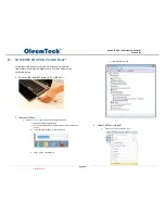
To perform this function, Gateway must be powered and 
connected to BreeZ® (Mini USB or Ethernet) 

a.


Connecting to device shows the current setup of Gateway only. 

b.


To change Gateway settings, you must access the properties by 
clicking “E” button or using edit command, then re-updating the 
Gateway. 


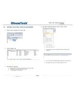
2.


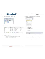
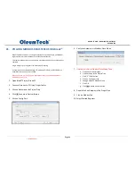
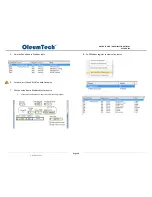
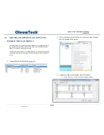
Click on Gateway in Project Tree and Click “Connect” Button 


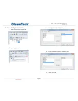
3.


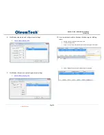
Device Tab 

a.


Displays how the device is set up 

b.


Displays Firmware version 


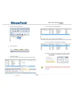
4.


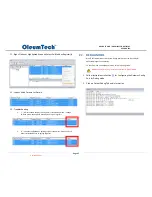
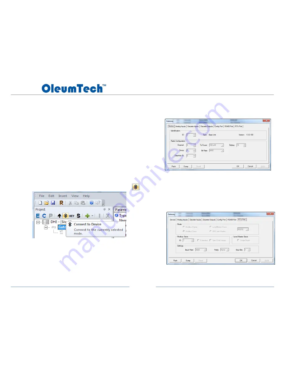
RTU Port Tabs 

a.


Displays how the RTU ports are set up 


Controlled Copy

Summary of Contents for WG-0868-DH1

Page 1: ...IRELESS GATEWAY USER GUIDE DH1 BASE UNIT WIRELESS GATEWAY WG 0900 DH1 WG 0915 DH1 WG 2400 DH1 WG 2410 DH1 WG 0868 DH1 DH2 WIRELESS GATEWAY WG 0900 DH2 WG 0915 DH2 WG 2400 DH2 WG 2410 DH2 WG 0868 DH2 U...

Page 2: ...C AND BreeZ 38 18 GATEWAY UPDATE FIRMWARE UPGRADE 40 19 CONNECT TO GATEWAY FUNCTION IN BreeZ 41 20 TRANSMITTER UPDATE CABLE METHOD PROGRAM CONFIGURE 43 21 POLLING MODBUS REGISTERS USING BreeZ 44 22 DE...

Page 3: ...TORS 12 MAPPING AN IMPORT TO AN OUTPUT ON DH1 BASE UNIT 51 MAPPING AN IMPORT TO AN OUTPUT ON WIRELESS MULTI I O MODULE 52 MODBUS MAPPING TABLE MANAGEMENT 30 MODBUS MASTER FUNCTION 58 MODBUS WRITE FUNC...

Page 4: ...G To prevent ignition of flammable or combustible atmospheres disconnect power before servicing AVERTISSEMENT Pour viter l inflammation d atmosph res inflammables ou combustibles d brancher l alimenta...

Page 5: ...Compliance Statement This equipment has been tested and found to comply with the limits for a class B digital device pursuant to Part 15 of the FCC Rules These limits are designed to provide reasonabl...

Page 6: ...s interf rences nuisibles dans une installation r sidentielle Cet quipement g n re utilise et peut mettre de l nergie radiofr quence et si non install et utilis conform ment aux instructions peut prov...

Page 7: ...s Peer to Peer Repeater Gateway to Gateway Works with Gateways Transmitters Wireless I O Modules RS485 I O Expansion System 1x RTU Ports Serial RS232 or RS485 Software Jumper Configurable Modbus Maste...

Page 8: ...a Modbus Master Modbus Slave LevelMaster Slave or ROC Link Master In a typical deployment DH1 Base Unit DH2 acts as a Modbus Slave device that is connected to a Modbus Master device such as a RTU PLC...

Page 9: ...Page 9 DH1 BASE UNIT DH2 WIRELESS GATEWAY USER GUIDE 4 HARDWARE OVERVIEW Controlled Copy...

Page 10: ...nsion System Configuration Cables USB to Serial Adapter SX1000 CC9 Gateway Configuration Cable SX1000 CC1 Software and PC BreeZ Software v5 0 or Higher Recommended Available on OleumTech Download Cent...

Page 11: ...up sequence is complete DH2 9 24 VDC Prior to SN SM11266715 LED will turn off once boot up is complete 6 Connect PC to Gateway see sec 17 a USB to Serial Adapter SX1000 CC9 b Gateway Configuration Cab...

Page 12: ...wing actions Check power source Replace radio module Call Tech Support State Green LED 1 Booting up Long blink 5 short blinks 2 Device On or Off Off 3 Connected to PC Updating in Progress Firmware Upg...

Page 13: ...iring diagrams and jumper settings to connect a third party device to the Wireless Gateway 1 SERIAL RTU Port DH1 Base Unit a DH1 Base Unit RS232 Field Wiring and Jumper Settings b DH1 Base Unit RS485...

Page 14: ...IT DH2 WIRELESS GATEWAY USER GUIDE 2 SERIAL RTU Port DH2 a DH2 RS232 Field Wiring and Jumper Settings b DH2 RS485 Half Duplex Wiring and Jumper Settings c DH2 RS485 Full Duplex Wiring and Jumper Setti...

Page 15: ...Pin Pin Name Generic Modbus Device 1 GND GND 2 Reserved 3 RX TX 4 RX TX 5 TX RX 6 TX RX 7 Reserved 8 Reserved Pin Pin Name PC Configuration Cable DB9 Pin Number 1 Reserved 2 DEBUG Ground 5 3 TXD RXD...

Page 16: ...the antennas from the enclosures use thickest washer on exterior side of enclosure TERRE DES MEILLEURES PRATIQUES Fran ias 1 Ne pas attacher TERRE les bornes de masse et de puissance num riques sans...

Page 17: ...cal Code CAUTION Ensure field wiring connections are in accordance with Article 504 of the National Electrical Code ANSI NFPA70 For more details on proper grounding electrodes and grounding electrode...

Page 18: ...ecured and retained connection IV Transient protection shall be provided on the supply to limit transients to a maximum of 42 Vpk INSTALLATION FRAN AIS La proc dure suivante d crit l installation corr...

Page 19: ...and connect MMCX end of the antenna cable to Gateway Radio listen for a click sound for confirmation b Connect Lightning Arrestor optional highly recommended c Drilling a hole may be required for rout...

Page 20: ...t vertical separation Ne installez pas autre antenne sur le m me plan vertical assurer la s paration verticale suffisante 4 Connect External Power a Gateway accepts 9 30 VDC 12 V recommended Use 18 24...

Page 21: ...added as a Modbus register for monitoring RF health Timeout trigger is normally set to three times the tx interval This means when the data packet is missed on three consecutive intervals attempts the...

Page 22: ...or higher Must update all devices in the project If an existing site has been enabled with AES encryption all wireless devices contained in that site must be updated with the revised BreeZ project fi...

Page 23: ...eeZ v5 x can open Project Files that are v3 3 0 109 or higher b BreeZ v5 x Project File cannot be opened using v4 x or v3 x c When opening Project File created using a previous version BreeZ v5 will a...

Page 24: ...and so on d Click Next 5 Configure Primary Wireless Gateway RTU Port 1 Settings a Create Gateway Name b Select Gateway Type DH1 Base Unit or DH2 c Select Tx Power Note Selecting higher Tx Power consum...

Page 25: ...RTD c Click Add button 7 Configure Transmitter a Create Transmitter Name b Enter Transmit Interval in Hour Minute Second c Select 16 bit or 32 bit Modbus Mapping Table i 16 bit adds to 3000 block ii...

Page 26: ...window i Click Next Battery Depletion Chart from 2 9 V Battery Voltage Tx Interval Duration Before Failure 2 9 V 1 second 1 hour 2 9 V 1 minute 2 days 2 9 V 5 minute 10 days 2 9 V 10 minute 20 days 2...

Page 27: ...e Type a Select RTD wiring mode that matches the Sensor 2 3 or 4 b 4 wire type is factory default for Direct Mount version RT1 c Click Finish 9 Confirm Transmitter Addition a Verify the added Transmit...

Page 28: ...other Transmitter or I O Module i Click on the Gateway in the Project Tree ii Click Insert button iii Select desired device d To add another Gateway i Click on Site in the Project Tree ii Click Insert...

Page 29: ...Page 29 DH1 BASE UNIT DH2 WIRELESS GATEWAY USER GUIDE 13 BreeZ MAIN SCREEN VIEW Controlled Copy...

Page 30: ...lect Delete function b Rearrange Use click and drag function of mouse c To add a register s see subsection 5 4 Export Modbus Mapping Table to View Outside of BreeZ a Click on File menu b Select Export...

Page 31: ...E 5 How to Add a Register from a Device a Single click on an end node in project tree b Click on E Edit button c Select a tag s from Exportable Tags box d Use the left arrow to move it over to Exporte...

Page 32: ...k on Modbus tab to verify added register k Option use the mouse to click and drag to desired position l 16 bit register starting point can be changed in BreeZ Range 0 3001 i Right click over any 16 bi...

Page 33: ...se Unit has six points of its own points that can be exported to the Modbus table a Analog inputs 1 4 b Discrete inputs 1 2 1 Double click on Gateway in project tree 2 Click on Imports tab 3 Select de...

Page 34: ...on b Rearrange Use click and drag function of mouse c To add a register s see subsection 5 9 Export Modbus Mapping Table to View Outside of BreeZ a Click on File menu b Select Export to CSV c Exported...

Page 35: ...onsumes more power 3 Serial RTU Port Tab a Allows configurations of Serial RTU port b RTU port can be set as a Modbus Master Modbus Slave LevelMaster ASCII Slave or ROC Link Master c Can be configured...

Page 36: ...e c Use the appropriate port settings to match with connecting device 5 Config Port Tab a Allows configurations of Config COM port b Mode i Modbus Slave enables Modbus poll write feature ii Debug enab...

Page 37: ...me edit name b Mode a Normally open b Normally closed c Count high d Count low e Count all c Debounce range 100 ms to 2000 ms 8 Discrete Outputs Tab DH1 Base Unit only d Name edit name e Options a Ini...

Page 38: ...e configured for use 1 Connect USB to Serial Adapter to PC s USB Port 2 Identify COM Port a Open Device Manager on your PC Using Windows 7 i Must have Admin rights to PC ii Click on Windows icon at bo...

Page 39: ...ice Manager vi Use dropdown box to select COM Port c DO NOT CHANGE THE BAUD RATE vii This baud rate setting is for your PC COM Port viii Wireless Transmitters are designed to only work with 57600 baud...

Page 40: ...pplication with F W upgrade to v2 x or higher F W v1 x only support up to first 256 import points 3 Update Gateway Firmware with Latest Version a Download Gateway Firmware from Download Center b Click...

Page 41: ...a log RTU and Ethernet port settings and changing date and time 1 To perform this function Gateway must be powered and connected to BreeZ Mini USB or Ethernet a Connecting to device shows the current...

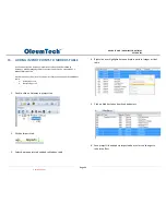
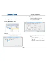
Page 42: ...Page 42 DH1 BASE UNIT DH2 WIRELESS GATEWAY USER GUIDE 5 Config Port Tab a Displays how the Config port is set up for connecting to PC Controlled Copy...

Page 43: ...Cable to USB to Serial Adapter c Connect Transmitter Configuration Cable to Gateway Configuration Cable d Connect Transmitter Configuration Cable to 4 pin connector 3 Update Upload Transmitter Using B...

Page 44: ...evice and network health When the Gateway s Config port is in Modbus Slave mode the Debug mode is disabled and vice versa 1 Open BreeZ Project File on PC 2 Connect Gateway to PC Using Proper Cables 3...

Page 45: ...indicates the Gateway s holding registers are empty Wait until fresh data is collected before re polling registers 22 DEBUG MODE BreeZ Software allows users to view debug information from Gateway for...

Page 46: ...etween Gateway to Gateway adding a RF refresh time tag to any of the shared points peer to peer can be very valuable 1 Double click on Gateway in project tree 2 Click on Modbus tab 3 Select a point ri...

Page 47: ...this point can be mapped to an output or shared with another device within the network A Master device connected to the Gateway have access to write to the same Modbus holding register s Last written...

Page 48: ...E 5 Point will be added to Modbus table 6 Save project file and MUST update Gateway 7 Write a value from a Modbus Master device a Values must be written as either 16 or 32 bit holding register 8 Poll...

Page 49: ...rade to v2 x or higher F W v1 x only support up to first 256 import points The transmit interval bit rate environment and number of interfering nodes play a significant factor in actual RF throughput...

Page 50: ...ary Gateway 10 Using shared point based on interval or on change a Double click primary Gateway b Click on Exports tab c Right click on point and select Interval d If time value equals 0 then the poin...

Page 51: ...ted by a Modbus Write function so that the point can be written by a third party Master device such a RTU or PLC 1 Create a Modbus Write function see sec 24 2 Share import point from Gateway to DH1 Ba...

Page 52: ...or another device with outputs An import point can also be a function created by a Modbus Write function so that the point can be written by a third party Master device such a RTU or PLC 1 Create a M...

Page 53: ...mports tab 6 Select desired point to be mapped to an output 7 Right click and select Copy 8 Click on Outputs tab 9 Right click over desired output target and select paste output source 10 Save project...

Page 54: ...2 output Added inputs can be mapped to Gateway s Modbus register table Added outputs become part of Gateway s routable outputs 1 Must have an available Serial RTU port on Gateway 2 Open a BreeZ proje...

Page 55: ...USER GUIDE 6 Click on Gateway in project tree and click Add Device button and select Modbus Module 7 Under IO Bus tab select desired RTU port or RS485 port a If using RTU port set Slave ID I O Module...

Page 56: ...tputs tab and configure output settings a Refer to Modbus mapping table 10 How to map inputs reads to Gateway s Modbus register holding table a Double click on Gateway in the Project Tree b Click on I...

Page 57: ...lect Modbus tab c Right click in the Window and select New Write Import d Create a name for the write command e Select Imports tab and right click on the newly created Write command and select Copy f...

Page 58: ...ding Registers FC3 int16 float 2 Read Input Registers FC4 int16 3 Write Single Holding Register FC6 int16 1 Determine if using RTU or RS485 port 2 Open a BreeZ project file 3 Access Gateway properties...

Page 59: ...GUIDE 5 RS485 port method DH1 Base Unit only a Click on RS485 port tab b Select Modbus Master for Mode of Operation c Configure rest of settings 6 Click on Gateway in project tree and click Add Device...

Page 60: ...t read interval and rest of settings 9 Click Modbus Outputs tab and configure output settings a Configure output settings 10 How to map inputs reads to Gateway s Modbus register holding table a Double...

Page 61: ...lect Modbus tab c Right click in the Window and select New Write Import d Create a name for the write command e Select Imports tab and right click on the newly created Write command and select Copy f...

Page 62: ...ts two Opcodes Opcode 17 login request Opcode 10 read configurable opcode data 1 Allows user to read up to 10 user configurable TLP points from a ROC 2 Points can be a mix of type INT16 signed or unsi...

Page 63: ...ule a Enter ROC information and Security if needed 4 Set Read Interval and Click Add Button to Add Points supports up to 10 points 5 Configure Points 6 Verify ROC Module Added in Project Tree Once Con...

Page 64: ...oject File The Project File can be retrieved from Gateway for use Note Every time a Project File is retrieved modified and used for updating devices be sure to save the revised file back onto the Gate...

Page 65: ...s 2 Open BreeZ Software 3 Close Project Creation Wizard Gateway power input spec to 9 30 VDC 4 Click R Retrieve Project File Button 5 Select a Location to Save the Retrieved File 6 Retrieved File Will...

Page 66: ...l site key can be viewed 2 File Saving Behavior in Relations to Site Security a Key will change when i Saving a new project file in BreeZ ii Changing a BreeZ file name using Windows Modifying file nam...

Page 67: ...cidentally to an existing project file the key can be retrieved from the Gateway b Connect Gateway to PC c Double click on Gateway in the project tree d Right click on Gateway then select Read Site Se...

Page 68: ...nfiguration Software User Guide Set the Retries setting for 16 if it has been changed see BreeZ Configuration Software User Guide Check Firmware of Device 3 DH1 Base Unit Reports Incorrect Measurement...

Page 69: ...nna should be installed at 10 ft or higher for better line of sight Wireless communication cannot reach Wireless Gateway Change the Bit Rate to the devices to 9600 Use a different Antenna type with hi...

Page 70: ...securely connected to the device and PC Verify the COM port settings in BreeZ are correct Verify the Baud Rate is 57600 and the Parity is 8 N 1 Connect another Transmitter to verify communication wit...

Page 71: ...1 Connect another Transmitter to verify communication with BreeZ Software Replace the Battery Pack Error while updating the device but connection is still present Verify that the device has the latest...

Page 72: ...in sound recording fluctuations in air pressure strike the diaphragm of a microphone inducing fluctuations in current produced by its coil This current is said to be an analog of the sound Analog Inp...

Page 73: ...umTech network device that monitors process conditions Enhanced Site Security Enabling site security reduces the chance that transmitted information can be accessed by unauthorized devices or cross ta...

Page 74: ...BreeZ software Pulsed The discrete output will change state for a specified period of time determined by a Modbus master via a Modbus register write The value written will be in milliseconds Range Ma...

Page 75: ...arate agreement depending on specific customer needs and applications b OleumTech warrants that goods repaired by it pursuant to the warranty are free from defects in material and workmanship for a pe...

Page 76: ...isclaims the implied warranties of merchantability and fitness for a particular purpose and makes no express warranties except as may be stated in its written agreement with and for its customers Oleu...

Reviews: