background image


Page 31


DH3 WIRELESS GATEWAY 

USER GUIDE 


a.


Verify the added Transmitter in the Device Table 

b.


Click 

Finish


c.


Click 

Confirm


11.


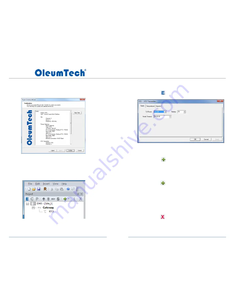
 Verify Project File 


a.


Review 

Project Tree

 window 

b.


To review or change device properties, 

i.


Click on the desired device in the Project Tree 

ii.


Click          (Edit) button 


c.


To add another Transmitter or I/O Module, 

i.


Click on the Gateway in the Project Tree 

ii.


Click          (Insert) button 

iii.


Select desired device 


d.


To add another Gateway, 

i.


Click on Site in the Project Tree 

ii.


Click          (Insert) button 

iii.


Select desired Gateway 
 

e.


To rename a device, 

i.


Right-click over a device in the Project Tree 

ii.


Select Rename 
 

f.


To remove a device from Project Tree, 

i.


Click on the desired device 

ii.


Click         (Delete) button 


Summary of Contents for WG-0900-DH3

Page 1: ...Page 1 DH3 WIRELESS GATEWAY USER GUIDE Based on Firmware v1 3 0 x RF2 DH3 WIRELESS GATEWAY WG 0900 DH3 WG 0915 DH3 WG 2400 DH3 WG 2410 DH3 User Guide...

Page 2: ...eeZ 43 24 ADDING IMPORT POINTS TO MODBUS TABLE 44 25 POLLING MODBUS REGISTERS USING BreeZ 45 26 EVENT LOGGING DATA LOGGING 46 27 TRENDING DATA LOGGING 50 28 WEB SERVER 54 29 RF REFRESH TIME TAG S 59 3...

Page 3: ...G AN IMPORT TO AN OUTPUT ON WIRELESS MULTI I O MODULE 65 MODBUS MAPPING TABLE MANAGEMENT 33 MODBUS MASTER FUNCTION 71 MODBUS WRITE FUNCTION AND WRITING TO DH3 60 NETWORK DIAGRAM 10 PEER TO PEER REPEAT...

Page 4: ...ammable or combustible atmospheres disconnect power before servicing AVERTISSEMENT Pour viter l inflammation d atmosph res inflammables ou combustibles d brancher l alimentation avant l entretien WARN...

Page 5: ...Compliance Statement This equipment has been tested and found to comply with the limits for a class B digital device pursuant to Part 15 of the FCC Rules These limits are designed to provide reasonab...

Page 6: ...es limites sont con ues pour fournir une protection raisonnable contre les interf rences nuisibles dans une installation r sidentielle Cet quipement g n re utilise et peut mettre de l nergie radiofr q...

Page 7: ...TECTURE The DH3 Wireless Gateway plays a vital role in the OleumTech Wireless Sensor Network When used as a primary Gateway it serves as the central collection point of data which then can be served t...

Page 8: ...ry Requirements Industrial Strength Performance and Durability BreeZ SOFTWARE Microsoft Windows based software tool for configuring Wireless Devices such as Wireless Transmitters Gateways and I O Expa...

Page 9: ...Page 9 DH3 WIRELESS GATEWAY USER GUIDE 5 HARDWARE OVERVIEW...

Page 10: ...Page 10 DH3 WIRELESS GATEWAY USER GUIDE DIMENSIONS 6 NETWORK DIAGRAM...

Page 11: ...igabit Ethernet Adaptor Software and PC Latest BreeZ Configuration Software Latest DH3 Gateway Firmware WT Series Firmware Update Utility Software Latest Transmitter Firmware Package PC with o Microso...

Page 12: ...ive with Firmware f Power cycle DH3 to reboot 8 Connect PC to DH3 see sec 20 a USB PC to Mini USB DH3 b Ethernet DHCP Static IP addressing Default Static IP 10 0 0 10 Default DH3 usernames and passwor...

Page 13: ...GATEWAY USER GUIDE 9 LED STATES STATUS INDICATORS During DH3 boot up LED 1 will be in the last known state at the time of shutdown Similarly LED 2 will be on during boot up with last known color at t...

Page 14: ...ERIAL AND POWER 1 Terminal Block is removable to facilitate wiring 2 Use BreeZ Software to configure Serial Ports a Right click on DH3 in Project Tree and select Edit b Click on RTU Port Tab 1 or 2 to...

Page 15: ...agonal viewable screen b Resistive type touch display c 640x480 screen resolution d Zero Configuration e Powered by DH3 f Optional 3ft extension adapter available g Auto sleep wake on touch h Manual 1...

Page 16: ...View RF network settings 7 Serial port screen a View the way serial ports are set up 8 Ethernet port screen a View Ethernet port settings b To view the current IP address from LCD the Ethernet port mu...

Page 17: ...e the antennas from the enclosures use thickest washer on exterior side of enclosure TERRE DES MEILLEURES PRATIQUES Fran ias 1 Ne pas attacher TERRE les bornes de masse et de puissance num riques sans...

Page 18: ...ical Code CAUTION Ensure field wiring connections are in accordance with Article 504 of the National Electrical Code ANSI NFPA70 For more details on proper grounding electrodes and grounding electrode...

Page 19: ...applicable local regulations INSTALLATION FRAN AIS La proc dure suivante d crit l installation correcte d un DH3 Avant d effectuer cette proc dure se assurer que le DH3 r pond aux exigences de mise l...

Page 20: ...o compress the spring loaded mechanism b Press Down on Clamp Lever and Latch Bottom Hooks c Another view 2 Insert Optional Micro SD Card for Data Logging a Use only industrial grade Micro SD Card part...

Page 21: ...face outer surface and inner wall of the hole drilled should be isolated from the antenna Use the rubber washers supplied by manufacturer to isolate the antennas from the enclosures use thickest washe...

Page 22: ...riented to the top position 1 Remove 5 screws and rotate bracket then re attach screws c Connect LCD cable to DH3 s LCD Port and tuck cable behind Display d Latch spring loaded side of bracket onto to...

Page 23: ...ry if you are seeing incorrect time stamping on data log or trend data a Remove 4 outer screws located on left and right side b Carefully remove top cover and remove 4 mounting screws c Carefully remo...

Page 24: ...can also be added as a Modbus register for monitoring RF health Timeout trigger is normally set to three times the tx interval This means when the data packet is missed on three consecutive intervals...

Page 25: ...ES encryption all wireless devices contained in that site must be updated with the revised BreeZ project file for the new encryption method to take into effect Otherwise the wireless device that are n...

Page 26: ...x can open Project Files that are v3 3 0 109 or higher b BreeZ v5 x Project File cannot be opened using v4 x or v3 x c When opening Project File created using a previous version BreeZ v5 will automat...

Page 27: ...e assigned Group 1 and so on d Click Next 5 Configure Primary Wireless Gateway RTU Port 1 Settings a Create Gateway Name b Select Gateway Type DH3 c Select Tx Power Note Selecting higher Tx Power cons...

Page 28: ...ent or Static IP Addressing b If using Static Addressing enter network information c For help setting up Ethernet connectivity please consult with your IT specialist 7 Add Transmitter WT Series RTD as...

Page 29: ...d settings Exported tags will automatically be added to the Modbus Mapping Table i Fahrenheit Temperature Unit ii Celsius Temperature Unit iii Battery Voltage Indicates Battery level 2 9 V is good iv...

Page 30: ...alth is strongly recommended If a new Battery Pack has been kept under storage or initially installed battery level may need to be read a couple of times to ensure a stable accurate reading Replace Ba...

Page 31: ...ject Tree ii Click Edit button c To add another Transmitter or I O Module i Click on the Gateway in the Project Tree ii Click Insert button iii Select desired device d To add another Gateway i Click o...

Page 32: ...Page 32 DH3 WIRELESS GATEWAY USER GUIDE 16 BreeZ MAIN SCREEN VIEW...

Page 33: ...ary a Remove Right click over desired register and select Delete function b Rearrange Use click and drag function of mouse c To add a register s see subsection 5 4 Export Modbus Mapping Table to View...

Page 34: ...DE 5 How to Add a Register from a Device a Single click on an end node in project tree b Click on E Edit button c Select a tag s from Exportable Tags box d Use the left arrow to move it over to Export...

Page 35: ...on Modbus tab to verify added register k Option use the mouse to click and drag to desired position l 16 bit register starting point can be changed in BreeZ Range 0 3001 i Right click over any 16 bit...

Page 36: ...a Allows configurations of two 2 serial ports b RTU port can be set as a Modbus Master Modbus Slave LevelMaster ASCII Slave or ROC Link Master c Can be configured to RS232 or RS485 d Use the appropri...

Page 37: ...ows using DHCP client or static addressing b Allows enabling or disabling of Modbus TCP IP services c Double click on Master row to change settings d Double click on Slave row to edit settings 5 USB P...

Page 38: ...en interfacing DH3 Creating unique login information is strongly recommended 1 Admin level access has the ability to change passwords and has read write access to DH3 using BreeZ a Default Admin Passw...

Page 39: ...vice settings BreeZ 3 View Debug information device activities BreeZ 4 Simultaneous Master Slave function TCP Ethernet port Default Static IP Address is 10 0 0 10 1 Update DH3 program BreeZ 2 Connect...

Page 40: ...ogram key that matches the project file 6 View Build Tab for confirmation When you see the message below you have successfully updated the DH3 If the message is something different be sure to repeat e...

Page 41: ...To perform this function DH3 must be powered and connected to BreeZ Mini USB or Ethernet a Connecting to device shows the current setup of DH3 only b To change DH3 settings you must access the propert...

Page 42: ...n manually set the date and time or use the Sync Local Time and use the PC clock and set the DH3 clock b Setting up the time and date becomes critical if data logging feature is enabled 22 DEBUG SESSI...

Page 43: ...xisting BreeZ project file containing a DH2 3 Open an Existing Project File with DH2 4 Right click on DH2 in Project Tree and Select Convert to DH3 5 Click Yes when prompted to save project file befor...

Page 44: ...ts own points that can be exported to the Modbus table a VIN Voltage Input b LogStatus Data Log Code 0 No logging 1 Logging 2 Logging Error 1 Double click on DH3 in project tree 2 Click on Imports tab...

Page 45: ...polling Use registers such as Battery Voltage RF timeout RF refresh and RSSI values to determine device and network health 1 DH3 Must be Powered and Connected to PC for this Operation 2 Open BreeZ Pr...

Page 46: ...ent and will write to it providing non volatile or persistent data If Micro SD Card is not detected it will write to internal RAM but data stored on RAM is volatile and will be lost when DH3 is power...

Page 47: ...ng triggered when equal or greater than threshold value b Falling triggered when equal or less than threshold value 8 Event Control select deadband or on delay a Deadband logs event when triggered by...

Page 48: ...Page 48 DH3 WIRELESS GATEWAY USER GUIDE 9 Enter Lower limit or On Delay time in seconds 10 Confirm logged point 11 Save project file and update DH3...

Page 49: ...xport Events Export Events button will be enabled if Event logging is enabled e Save CSV file to preferred destination 13 Open csv file to view data log 14 If seeing incorrect time stamping on data lo...

Page 50: ...etected it will write to internal RAM but data stored on RAM is volatile and will be lost when DH3 is power cycled or updated If Micro SD Card is removed while operating DH3 will switch and write to R...

Page 51: ...s and sampling interval i Data that passes the set duration will be thrown out d Trend Point s points in this table will be used for trending e Import Point s points available that can be added to tre...

Page 52: ...ght click and select Y Axis c Use drop down menu to select Y Axis 8 How to Modify a Created Trend a Click on Trending tab b Select a desire trend group right click and select Modify 9 How to Enable or...

Page 53: ...d groups into one csv file b Connect to DH3 c If trending is enabled Export Trends button will be enabled d Click on Export Trends button e Select location and save csv file f Open csv file g If seein...

Page 54: ...ication line Internet Browser for Using DH3 Web Server Microsoft Internet Explorer v10 or later Google Chrome v39 0 or later Mozilla Firefox v32 0 or later Remote Access Ethernet If you are trying to...

Page 55: ...ompted by This Connection is Untrusted For Chrome a Click Advanced b Click Proceed to For Internet Explorer a Click Continue to this website For FireFox a Click I Understand the Risks option b Click A...

Page 56: ...ogo or home icon to return to this page 9 Modbus Page a Use refresh button to poll latest data b Use filter option to change view per device 10 Events Page a System tab i Use refresh button to poll la...

Page 57: ...amount of data ii User refresh button to update trend graph c System events are automatically logged providing additional analytical information d Zoom In Click and drag a section of the range to zoo...

Page 58: ...Page 58 DH3 WIRELESS GATEWAY USER GUIDE 12 Radio Page 13 Ethernet Port Page 14 Serial Ports Page...

Page 59: ...e between Gateway to Gateway adding a RF refresh time tag to any of the shared points peer to peer can be very valuable 1 Double click on DH3 in project tree 2 Click on Modbus tab 3 Select a point rig...

Page 60: ...this point can be mapped to an output or shared with another device within the network Multiple Master devices connected to the DH3 all have access to write to the same Modbus holding register s Last...

Page 61: ...UIDE 5 Point will be added to Modbus table 6 Save project file and MUST update DH3 7 Write a value from a Modbus Master device a Values must be written as either 16 or 32 bit holding register 8 Poll M...

Page 62: ...peer application The transmit interval bit rate environment and number of interfering nodes play a significant factor in actual RF throughput and peering capabilities 1 Click on Site level in project...

Page 63: ...Gateway 10 Using shared point based on interval or on change a Double click primary Gateway b Click on Exports tab c Right click on point and select Interval d If time value equals 0 then the point w...

Page 64: ...by a Modbus Write function so that the point can be written by a third party Master device such a RTU or PLC 1 Create a Modbus Write function see sec 30 2 Share import point from DH3 to Base Unit usi...

Page 65: ...Base Unit Wireless Multi I O Module or another device with outputs An import point can also be a function created by a Modbus Write function so that the point can be written by a third party Master d...

Page 66: ...Imports tab 6 Select desired point to be mapped to an output 7 Right click and select Copy 8 Click on Outputs tab 9 Right click over desired output target and select paste output source 10 Save projec...

Page 67: ...output Added inputs can be mapped to DH3 s Modbus register table Added outputs become part of DH3 s routable outputs 1 Must have an available Serial RTU port on DH3 2 Open a BreeZ project file contain...

Page 68: ...tton and select Modbus Module 7 Under IO Bus tab select desired RTU port or Ethernet port a If using RTU port set Slave ID I O Module ID on rotary switch dial 1 b If using Ethernet port set Slave ID I...

Page 69: ...Outputs tab and configure output settings a Refer to Modbus mapping table 10 How to map inputs reads to DH3 s Modbus register holding table a Double click on Gateway in the Project Tree b Click on Im...

Page 70: ...Select Modbus tab c Right click in the Window and select New Write Import d Create a name for the write command e Select Imports tab and right click on the newly created Write command and select Copy...

Page 71: ...3 int16 float 2 Read Input Registers FC4 int16 3 Write Single Holding Register FC6 int16 1 Determine if using RTU or Ethernet port on DH3 2 Open a BreeZ project file containing a DH3 3 Access DH3 prop...

Page 72: ...UIDE 5 Ethernet port method a Click on Ethernet port tab b Double click on Modbus TCP IP Master row c Check box to enable Master mode of operation 6 Click on Gateway in project tree and click Add Devi...

Page 73: ...If using RTU port select Slave ID b If using Ethernet port select Slave ID and port address and IP address 8 Click Modbus Inputs tab and configure input settings a Set read interval and rest of setti...

Page 74: ...orts tab c Right click over import points and select paste to Integer or float table d Select Modbus tab and verify Modbus register mapping 11 How to write to outputs using third party Modbus Master d...

Page 75: ...e Select Imports tab and right click on the newly created Write command and select Copy f Select Outputs tab and right click on an output point and select Paste Output Source g Save project file h Upd...

Page 76: ...upports two Opcodes Opcode 17 login request Opcode 10 read configurable opcode data 1 Allows user to read up to 10 user configurable TLP points from a ROC 2 Points can be a mix of type INT16 signed or...

Page 77: ...Module a Enter ROC information and Security if needed 4 Set Read Interval and Click Add Button to Add Points supports up to 10 points 5 Configure Points 6 Verify ROC Module Added in Project Tree Once...

Page 78: ...ower Cycle DH3 or Press and Hold Reset Button for 3 Seconds to Initialize Firmware Upgrade a If DH3 connected to Local Display click OK on screen when prompted DO NOT UNPLUG USB FLASH DRIVE UNTIL UPGR...

Page 79: ...rt must be configured for use 1 Connect USB to Serial Adapter to PC s USB Port 2 Identify COM Port a Open Device Manager on your PC Using Windows 7 i Must have Admin rights to PC ii Click on Windows i...

Page 80: ...vice Manager vi Use dropdown box to select COM Port c DO NOT CHANGE THE BAUD RATE vii This baud rate setting is for your PC COM Port viii Wireless Transmitters are designed to only work with 57600 bau...

Page 81: ...Cable to USB to Serial Adapter c Connect Transmitter Configuration Cable to Gateway Configuration Cable d Connect Transmitter Configuration Cable to 4 pin connector 3 Update Upload Transmitter Using...

Page 82: ...ate Gateway Firmware to Version 1 4 0 94 or Higher v2 0 or Higher Recommended a Required for use with WT Series Transmitters b Download Gateway Firmware from Download Center c Click on Gateway in the...

Page 83: ...roject File The Project File can be retrieved from Gateway for use Note Every time a Project File is retrieved modified and used for updating devices be sure to save the revised file back onto the Gat...

Page 84: ...Close Project Creation Wizard 4 Click R Retrieve Project File Button a Select Gateway type from dropdown menu 5 Enter Credentials and Choose Connection Type 6 Select a Location to Save the Retrieved...

Page 85: ...site key can be viewed 2 File Saving Behavior in Relations to Site Security a Key will change when i Saving a new project file in BreeZ ii Changing a BreeZ file name using Windows Modifying file name...

Page 86: ...ccidentally to an existing project file the key can be retrieved from the Gateway b Connect Gateway to PC c Double click on Gateway in the project tree d Right click on Gateway then select Read Site S...

Page 87: ...Page 87 DH3 WIRELESS GATEWAY USER GUIDE 44 RESETTING DH3 PASSWORDS 1 Right click on a DH3 in Project Tree and select Reset Passwords 2 Select connection type...

Page 88: ...nter s password reset page http support oleumtech com dh3 reset passcode User must have access to support oleumtech com 4 Copy and paste DH3 MAC address and Unique Key then click Generate Reset Passco...

Page 89: ...ault username admin and password admin select connection type then click OK 7 Enter new passwords for desired level of access then click OK Repeat this step to change password for other levels 8 Confi...

Page 90: ...RF traffic and makes better usage of RF bandwidth Additionally local I O Modbus and ROC Link Modules may be disabled causing their associated Modbus Master requests to be ignored by the Gateway elimin...

Page 91: ...Modbus tab shown register positions are held even when disabled 3 If file is being utilized for a new site use the Save As function to assign a new site security for the Project File 4 Update impacte...

Page 92: ...wer supply with a minimum of 380 mA and correct polarity a Upon applying power to the DH3 both LEDs should turn on and then turn off after about 25 seconds 2 If connecting through the USB a USB to Min...

Page 93: ...llation was complete d If step c does not work for Windows 7 based OS then use the helpful link below http developer toradex com knowledge base how to install microsoft rndis driver for windows 7 2 DH...

Page 94: ...ng devices Confirm that the antennas of all devices have a clear line of sight and are within recommended distances Increase the Tx Power of all devices Verify transmitter interval settings be sure to...

Page 95: ...ctions to reset the password The following is required to perform the reset Download Center Access http support oleumtech com Internet connectivity to access Download Center Local connection to DH3 8...

Page 96: ...enna should be installed at 10 ft or higher for better line of sight Wireless communication cannot reach Wireless Gateway Change the Bit Rate of the devices to 9600 Use a different Antenna type with h...

Page 97: ...s securely connected to the device and PC Verify the COM port settings in BreeZ are correct Verify the Baud Rate is 57600 and the Parity is 8 N 1 Connect another Transmitter to verify communication wi...

Page 98: ...1 Connect another Transmitter to verify communication with BreeZ Software Replace the Battery Pack Error while updating the device but connection is still present Verify that the device has the lates...

Page 99: ...in sound recording fluctuations in air pressure strike the diaphragm of a microphone inducing fluctuations in current produced by its coil This current is said to be an analog of the sound Analog Inpu...

Page 100: ...leumTech network device that monitors process conditions Enhanced Site Security Enabling site security reduces the chance that transmitted information can be accessed by unauthorized devices or cross...

Page 101: ...using BreeZ software Pulsed The discrete output will change state for a specified period of time determined by a Modbus master via a Modbus register write The value written will be in milliseconds Ran...

Page 102: ...parate agreement depending on specific customer needs and applications b OleumTech warrants that goods repaired by it pursuant to the warranty are free from defects in material and workmanship for a p...

Page 103: ...st Revision E Added major factors to actual peer to peer capabilities in section 31 Revision F Revised best grounding practices section 9 Revision G Revised section 27 trending max range to 90 days Up...

Page 104: ...pose and makes no express warranties except as may be stated in its written agreement with and for its customers OleumTech shall not be held liable to anyone for any indirect special or consequential...

Reviews: