background image

2  


EN 

1. GENERAL WARNINGS 

- Read this manual carefully before installing this pump. 
It contains every necessary information for installation, 
correct use and maintenance of CMV pumps. 
-  It's  very  important  that  the  user  reads  this  manual 
before using the pump. Any damage caused by failure 
to observe the directions contained in this manual will 
not be covered by warranty. 

- By the time you receive this pump check 
if  it  wasn´t  damaged  during  transpor-
tation. 

-  In  this  case,  please  contact  our  agent  as  soon  as 
possible. 


2. OPERATING CONDITIONS: 

- The CMV are centrifugal multistage pumps and have 
been designed to work with clean water at a maximum 
temperature of 35º C. 
- Maximum starts/hour: 30 at regular intervals. 


3. INSTALLATION: 

-  The  pump  should  be  fixed  to  a  solid  base  by  bolts 
through the holes in the bottom of the pump in order 
to prevent unwanted noise or vibration. 

-  You  should  place  pump  as  near  as 
possible  to  water  level  so  to  have  the 
minimum  suction  lift  and  reduce  loss  of 
head. 

- Make sure that pump is never submerged and that it 
rests in a dry and well aired room. 


4. PIPES ASSEMBLY: 

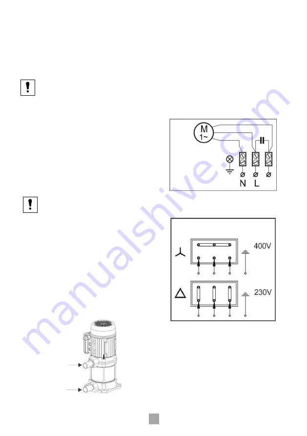
-  Suction  pipe  (Pic.  1)  must  be  the  same  or  lower 
diameter than the pump inlet and must always remain 
in na upward inclination of 2% so to help with correct 
priming. 
-  A  foot  valve  with  filter  should  be  installed  and 
submerged  to  at  least  30cm  below  the  well  dynamic 
level to prevent air from entering the pump. 
- Be sure that discharge pipe (Pic. 1) should never rest 
on top of the pump. 


5. ELECTRICAL CONNECTION: 

-  The  single-phase  motors  have  a  built-in  thermal 
protection. 
-  The  electrical  installation  must  have  a  system  of 
multiple separations with contact opening of at least 3 
mm. 
-  The  protection  of  the  system  will  be  based  on  a 
differential swith ( I fn = 30 ma). 
-  The  electric  cable  must  correspond  to  the  EEC  (2) 
norm or to the type H07 RN-F. 
-  With  three-phase  motors,  end-user  must  install 
himself the correct protection to the pump as per the 
aproppiate installation regulations. 


-  Follow  directions  on  Pic.3.  for  a  correct  electrical 
connection. 


6. CONTROLS PRIOR TO THE INITIAL 
STARTING: 

- Check that voltage and frequency correspond to 
those indicated on the technical characteristics label. 

- Make sure the motor shaft is turning freely. 

- Fill pump body completely with water, as well as the 
suction pipe, through the priming hole (Pic. 4). Check 
that there is no leaking through joints or connections. 

Pic.1 

DELIVERY 

SUCTION PIPE 

Pic.2 

SINGLE PHASE 

SUPPLY 

Pic.3 

THREE PHASE SUPPLY 

Summary of Contents for CMV Series

Page 1: ...CMV FR IT ES EN PT OLIJU INSTRUCTIONS Installation and operation instructions The realiability is our brand...

Page 2: ...or lower diameter than the pump inlet and must always remain in na upward inclination of 2 so to help with correct priming A foot valve with filter should be installed and submerged to at least 30cm...

Page 3: ...ity persisted pump should be cleaned and stored in a dry aired room 9 FAULT FINDING CHART Before attempting to diagnose any fault make sure that the electricity supply has been switched off FAULT CAUS...

Page 4: ...o orif cio de entrada da bomba conservando uma inclina o ascendente de pelo menos 2 para facilitar a purga imprescind vel a coloca o de uma v lvula de p com filtro submersa pelo menos 30 cm abaixo do...

Page 5: ...to tempo deve limpar se a bomba e guard la em lugar seco e ventilado 9 AVARIAS E CAUSAS Antes de tentar diagnosticar qualquer avaria verifique se a alimenta o el ctrica foi desligada AVARIA CAUSA POSS...

Page 6: ...ferior al de laboca de entrada de la bomba permanentemente una pendiente ascendente m nima del 2 para que contribuya a efectuar una purga correcta Es imprescindible una colocaci n de una v lvula de pi...

Page 7: ...a a trav s del tap n de purga Fig 5 Si la inactividad persistiera debe limpiarse la bomba y aguardarse en lugar seco y ventilado 9 LOCALIZACI N DE FALLOS Antes de intentar diagnosticar un fallo compro...

Page 8: ...ifice d aspiration de la pompe et maintenir une pente ascendante d au moins 2 pour permettre une bonne purge de la tuyauterie Il est n cessaire d installer un clapet de pied cr pine immerg au moins 30...

Page 9: ...poursuit il convient de nettoyer la pompe et de la ranger dans un endroit sec et a r 9 RECHERCHE DES PANNES Avant d effectuer toute sorte d op rations s assurer que l alimentation lectrique ait bien...

Page 10: ...aria che raffredda il motore deve essere secca 4 MONTAGGIO DELLA TUBAZIONE La tubazione d aspirazione Fig 1 deve avere un diametro uguale o leggermente inferiore a quello della bocca d aspirazione del...

Page 11: ...LA RICERCA GUASTI Prima di procedere al rilevamento dei guasti togliere tensione alla pompa GUASTO DIFETTO CAUSA La pompa non parte Falha na corrente de energia Circu to de controlo est desligado ou d...

Page 12: ...ciones de seguridad de la Directris 2006 42 CE EN ISO 12100 EN 60335 1 EN 60335 2 41 2004 108 CE D CLARATION DE CONFORMIT Les produits vis s dans la presente d claration sont conformes la directive 20...

Reviews: