As electrobombas referidas nesta declaração,
estão em conformidade com a Directiva
73/23/CEE
(Directiva de Baixa Tensão). A plena
concordância com os requesitos essenciais da
Directiva é comprovada pela conformidade com
a norma
EN 60335-2-41
.
(Gerencia)
ENGLISH
-
Before carrying out checks
or doing any maintenance, clear
the system by disconnecting the
voltage, unplug the pump from
the socket and then rinse the
pump well with clean water.
- They are not suitable for
pumping inflammable liquids or
for operating in places where is
danger of explosion. Avoid contact
between the power supply and the
liquid to be pumped. Do not modify
the components of the water pump.
- The water pumps comply with the EEC
Directives 73/23/EEC, 98/037/EEC,
89/336/EEC including the latest amendments.
- Before installing the water pump, make
sure that the power supply mains is earthed
and complies with regulations.
1 - GENERAL WARNINGS
- These pumps are recommended for pumping
very dirty and sewage water. They must be used
in compliance with local laws.
- Before installation and use read the
following instructions carefully. The
manufacturer declines all responsibility in the
event of accident or damage due to negligence
or failure to observe the instructions described
in this booklet or in conditions that differ from
those indicated on the rating plate. It also
declines all responsibility for damage caused by
improper use of the water pump.
- When storing, do not pile weights or other
boxes on top.
2 - SAFETY
- The water pump must never be
lifted or transported by its supply
cable or float switch; it must be
held by the appropriate handgrip.
- Keep hands or other object away from the
hole under the pump casing near the
supporting feet.
- Do not use the pump in swimming pools,
garden ponds or similar places when people
are in the water.
4 - CONDITIONS OF USE
- The following conditions must be observed when
using the water pump::
a
Maximum fluid temperature: 40ºC.
a
Maximum density of the liquid pumped: 1,1
3
Kg/dm .
a
pH of the liquid: 5 / 9
a
Vo l t a g e v a r i a t i o n a l l o w e d : ± 5 %
(in the case of single-phase voltage
220/240V and three-phase voltage 380/415V
, these are the permitted limit values).
a
Protection index: IP 68
a
Max. immersion depth: 3 to 5 m.
- Unpack and check that it is in
perfect condition. Also check that the
data on the rating place correspond to
the required data.
3 - PERLIMINARY INSPECTION
- If there is any problem contact the supplier
immediately, specifying the type of fault.
- CAUTION: If there is any doubt about
the safety of the machine, do not use it.
ENGLISH
- Do not underestimate the risk of drowning
if the installation has to be performed in a well
at a certain depth.
- Make sure there are no toxic discharges or
harmful gases present in the atmosphere. If the
installation involves welding, take all necessary
precautions to avoid explosions.
- Always remember the danger of infection
and take all hygiene-health precautions.
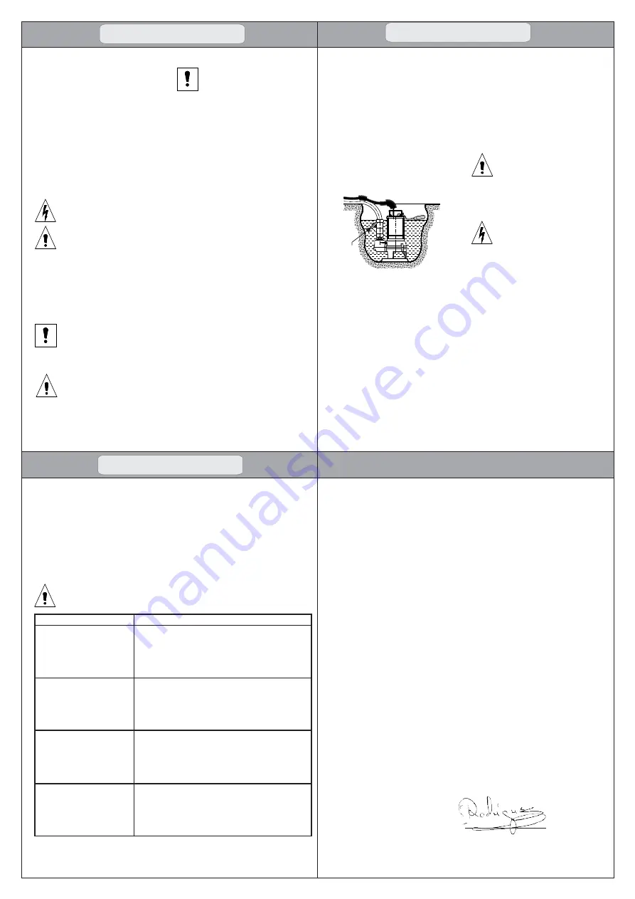
- If the bottom of the well or the surface on
which the pump rests is uneven and there is the
possibility of stones, debris, mud, etc.,
accumulating there, lay a level raised supporting
base (Fig. 1).
- The delivery piping may be either rigid or
flexible as long as the cross-section for passage
of the fluid is no smaller than that of the pump
delivery outlet.
- CAUTION: it is the installer's
responsibility to perform the connections in
compliance with the regulations in force in
the country of installation. Make sure that
there is no voltage at the line wire terminals
before connecting.
- Check that the data on the rating plate
corresponds to the rated line values.
CHECK
V
AL
VE
Fig. 1
ENGLISH
- You are advised to check the following
periodically:
a
The condition of the cables and
grommets, especially at their
attachment points.
a
T h e i m p e l l e r m u s t n o t b e
e x c e s s i v e l y w o r n , o t h e r w i s e
performance will be reduced.
- Consult our services for replacement.
- When carrying out connections
make sure that there is an efficient
earth circuit. The earth wire must be
longer than the live wires, and must
be the first wire to be connected
when the pump is being set up and
the last to be disconnected during
disassembly.
- It is advisable to install a
differential switch. A thermal
overload cutout in the winding
protects against voltage overload in
the single-phase pump motors up to
1.5 KW.
- The three-phase motors must be
protected by the user.
- For three-phase motors the rotation
direction may be inverted; in this case
performance is much lower than the rated
values.
- The correct direction of rotation is found
by raising the water pump by its handgrip:
during starting a clockwise reaction will be
felt (contrary to the direction of the arrow) to
invert the direction of rotation simply invert
two of the phases.
- CAUTION: Never poke fingers or other
objects into hole the pump casing near the
supporting feet to check the direction of
rotation.
- Repair of the pump by personnel not
authorized by the manufacturer will
render the guarantee null and void and will
entail operating dangerous equipment.
-
CAUTION: Any tampering may lead
to performance being reduced and
danger to persons and/or things.
- Where there is the risk of freezing, empty the
well or remove the pump and store it in a suitable
place.
7 - PERIODICAL CONTROLS
- Before doing anything, make sure that the
pump is disconnected from the power source and
there is no possibility of accidental connections.
8. FAULT FINDING CHART
Pump runs constantly or
gives insufficient water.
Pump runs but gives no water.
Motor does not start.
- No electricity supply.
- Motor switched off by level switch.
- Fuses are blown.
- Impeller blocked by impurities.
- Short-circuit in cable or motor.
- Temperature of pumped liquid too high.
- Impeller blocked or partly blocked by impurities.
- Phase failure.
- Voltage too low.
- Pump blocked by impurities.
- Discharge pipe blocked by impurities.
- Liquid level too low. The pump inlet is not completely
submerged in the pumped liquid.
- Pump partly blocked by impurities.
- Discharge pipe partly blocked by impurities.
- Incorrect direction of rotation.
- Pump too small for the application.
FAULT
CAUSE
Thermal relay trips out after
short time of operation.
If in spite of carryng out the above operations, the problem still
persists contact the nearest service centre.
Before attempting to diagnose any fault, make sure that the
electricity supply has been switched off.
The products , referred to in this statement are
in accordance with Directive
73/23/EEC
(the
Low Voltage Directive). Full compliance
with essential requirements of the Directive is
verified for compliance with standard
EN
60335-2-41
.
a
Minimum emptying level:
F 40: 90mm
F 50: 100mm
F 65: 120mm
a
M a x i m u m d i a m e t e r o f s o l i d
particles sucked up:
F 40: 38mm
F 50: 50mm
F 65: 63mm
a
For intermittent duty the water
temperature may reach + 60ºC.
5 - INSTALLATION
- Installation can be a fairly complex
operation.
- It must therefore be carried out by competent
and authorized installers.
- CAUTION: during installation apply all
safety regulations issued by the competent
authorities and use common sense al all times.
- To avoid the backflow of liquid from the
discharge manifold, install a check valve after
the pump delivery outlet (Fig. 1).
- If the pump is installed in a well, the well
must measure at least:
F 40: 400x400x400
F 50: 500x500x500
F 65: 600x600x600
- The starting and stopping level of the pump
can be varied by increasing the free length of
the float.
- For the motor to be cooled correctly the
water level should not drop below :
F 40: 250mm
F 50: 300mm
F 65: 400mm
6 - ELECTRICAL CONNECTIONS
- They are delivered ready to be connected.


