OLIMEX© 2015
A20-OLinuXino-MICRO user's manual
6.2.2 SD/MMC slot
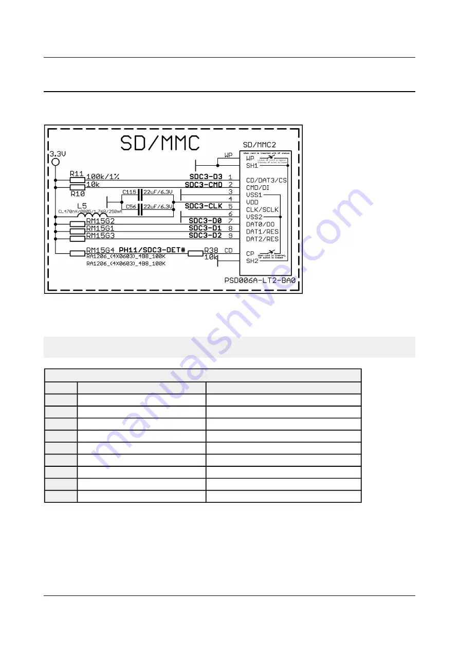
The schematic related to the SD/MMC1 (SD/MMC connector) is shown below:
The SD/MMC2 slot is located on the back of the PCB and works with the “larger” SD and MMC
cards. The connector was placed by a popular demand.
Note that by default this connector is not suitable for booting OS. Such support is possible but not
implemented in the official software releases.
SD/MMC card connector
Pin # Connector signal name
Wire name (processor pin)
1
CD/DAT3/CS
SDC3-D3 (B16)
2
CMD/DI
SDC3-CMD (A18)
3
VSS1
-
4
VDD
-
5
CLK/SCLK
SDC3-CLK (B18)
6
VSS2
-
7
DAT0/DO
SDC1-D0 (A17)
8
DAT1/RES
SDC1-D1 (B17)
9
DAT2/RES
SDC1-D2 (A16)
Additionally, there are the WP and CP switches that are responsible, respectively, for sensing
whether the card is locked for reading and whether there is a card inserted.
Page 29 of 56


